How to Build a Sailboat Rudder From Scratch


Introduction: How to Build a Sailboat Rudder From Scratch

Step 1: Previous Rudder

Step 2: Rebuild

Step 3: Sanding

Step 4: Fiberglass Layup

Step 5: First Layer and Sanding

Step 6: Additional Layers and Difficult Spots

Step 7: Notes of Caution

Step 8: Hardware Holes

Step 9: Painting

Step 10: The End!

Building, restoration, and repair with epoxy

How to Build Rudders & Centerboards
by Captain James R. Watson
When the centerboard of my Searunner trimaran broke in the middle of a windy race around the Black Hole, the question I kept asking was “Why now, after working fine all of this time, and when we were leading the race?”
“Guess it just wore out” was my excuse to myself. This centerboard was built of laminated layers of plywood, resulting in a thickness of 2″. It was then covered with two layers of 6-oz woven fiberglass fabric. It was a deep and wide board with a lot of area, and like any rudder or centerboard on a boat that is sailed hard, it was exposed to a fair amount of stress.
The answer to “Why now – while leading the race?” could have been fate. But there is a more scientific answer. Extensive laboratory testing at Gougeon Brothers, Inc. defines why the centerboard failed. Understanding why can help us design and construct components that will perform more efficiently and last much longer.
The plywood centerboard did, in fact, wear out – or more accurately – it failed from rolling shear fatigue. Fatigue cracks in a material result from repeated (cyclic) stress. Fatigue is a reality of all structures and materials and eventually culminates in structural failure. Repeated loading and unloading or even worse, loading one way and then the other (reverse axial), rapidly reduces a material’s physical integrity and accelerates degradation. The higher the load is as a percentage of the material’s ultimate strength, the more rapid is the deterioration.
Some materials have a greater fatigue life than others. Ounce per ounce, wood is capable of operating at a much higher percentage of its ultimate stress level than most other materials. That is why such wonderfully efficient structures can be built with wood. However, plywood is not a good choice for cantilevered structures such as rudder blades and centerboards. This is because plywood is susceptible to rolling shear, shearing forces that roll the structural fibers across the grain. Plywood’s unidirectional wood fibers are laid in alternating layers, approximately half of them are oriented 90 degrees to the axis of the loads. Like a bundle of soda straws, which resist bending moments quite well one way, they simply lack cross-grain strength laterally and can roll against one another and fail under relatively low stress, especially in a cyclic environment. Therefore, when anticipated loads are primarily unidirectional, it is ideal to use a material with good unidirectional strength. Since only half of the plywood’s wood fiber is used to advantage, a plywood rudder blade or centerboard going from tack to tack (reverse axial loads) will fatigue much more rapidly than one built as described in this article.
If you were to look at the end of the board, say a fish’s view of a centerboard or rudder blade, you’d view its cross-section. A section that has a faired airfoil shape is preferred over one that is flat with parallel sides. This is because the airfoil shape produces lift when moving through the water, thereby counteracting the sideward forces exerted by the sail rig. A flat section produces less lift and at a great expense of drag, slowing the boat and making it more difficult to steer.

“Turn every other ripping end-for-end to neutralize the effects of any grain that does not run exactly parallel to the blank, and to reduce tendencies to twist. Rotate the rippings 90 degrees to expose the vertical grain and to permit easier shaping with a plane.
The selection of a proper camber and section can be a subject of great theoretical debate. One can become intimidated with technical terms such as thickness distribution, Reynolds number, boundary layer, and so on. These terms do relate to the subject, however, for the builder/sailor whose boat floats forlornly in need of a rudder blade the following will do just fine. In fact, the best designers and builders will be hard-pressed to do better.
An excellent choice for most craft is a realistically accurate and fair NACA (National Advisory Committee for Aeronautics) 0012 airfoil, where maximum board thickness is 12% of the fore/aft length (chord length). Maximum thickness is located about 30% of the chord length measured from the leading edge (see sketch). The dimensions used to establish a specific shape (called offsets) are given in the appendix of Abbott & Doenhoff’s The Theory of Wing Sections. You’ll also find further information in my article How to loft Airfoil Sections.
From offsets make a good drawing of half the section on transfer paper.
Western red cedar and redwood are good choices of wood to use for rudder blades and centerboards for boats up to 25 feet. Both of these woods bond very well are generally clear and straight-grained, have good dimensional stability, are easily worked and affordable. Cedar is just a little heavier than the foams used for rudders, is much stiffer, and has far greater shear strength values. On larger craft, a higher-density material like African mahogany is a better choice. Oak is not a good choice.
Buy flat-grained 2’x6″s or 2’x8″s, and then rip them to the designed board thickness. Turn every other ripping end-for-end to neutralize the effects of any grain that does not run exactly parallel to the blank, and to reduce tendencies to warp or twist (see sketch). Rotating the rippings 90 degrees to expose vertical grain will permit easier shaping with a plane. The last trick is to rip the end pieces of the nose and tail in half. Bonding with a couple of layers of glass tape between keeps the fine edge of the tail from splitting too easily and offers a precise centerline.
Bond the ripping with a slurry of epoxy and 404 High-Density filler. Plastic strips prevent inadvertent bonding to leveled sawhorses (see sketch). With both sawhorses leveled, you’re positive no twist exists in the laminated blank. Bar clamps should be snugged until excess glue squeezes from the joints. Over tightening only stresses joints and tends to squeeze all the adhesive from them. When the laminate is cured, a light planing to clean the surfaces is all that is needed before shaping begins.

Centerboards and rudder blades are often overlooked components that are vital to a boat’s performance.
First, tack the 1/8″-thick plywood template that describes the cross-section shape to the blank’s ends. This is sawn from the impression made when traced with the transfer paper you originally drew it on. The key to producing an accurate and symmetrical board is maintaining a systematic removal of material from one side, then from the other. To do this, mark the shape to be removed, stick to straight-line shapes (see sketch). Use a smoothing plane to remove the wood.
After planing to the guidelines on one side, flip the blank over and plane the same shape on the other side. The procedure is similar to producing a round shape from a square by first forming an octagon, and then flattening the resulting eight corners to produce a 16-sided shape and refining that until very minute flat surfaces exist. Fifty-grit sandpaper bonded with 3M brand feathering disc adhesive to a 1/2″-thick by 11’x4.5″-wide plywood sanding block is a good tool to use for fairing this out.
Now you should decide if the board needs reinforcement. Your board requires reinforcement if the chord thickness is at or below 4% of the unsupported span. The unsupported span of a daggerboard or centerboard is that measurement from where it exits the hull, to its tip when fully lowered. The unsupported span of the rudder blade is the distance from the rudder case to the tip. If it is a non-retracting blade, measure from the waterline to the tip. So, if the board extends 48″ below the bottom of the hull and is 2″ thick, .04″, it should be reinforced for strength and stiffness.
If the board needs reinforcement, graphite fibers are a good choice as the strain-to-failure values of wood and graphite fiber are quite similar, hence they enhance each other’s performance. The high-modulus qualities of the graphite fibers provide stiffness. The addition of graphite will efficiently increase stiffness and ultimate strength. Don’t be intimidated by the high-tech qualities of graphite fibers, they are easy to work with.
The amount of reinforcement needed is usually figured at 10% chord thickness. Using the same board for our example, the board is 2″ thick, then 10% equals .20″ total reinforcement, .10″ per side. Graphite fiber tows are .01″ thick, so 10 tows per side should give the necessary reinforcement to do the job.

The graphite fibers will be laid into a channel routed into the shaped centerboard.
The graphite fibers will be laid into a channel that is routed into the shaped board (see sketch). The specific depth of the channel is determined by the above rule. Make the channel a little deeper than what’s required (1/16″) so you won’t be sanding the graphite fibers.
The profile of the channel is similar on all boards. The centerline of the channel is usually located at the point of maximum chord thickness (about 30% from the leading edge). The widest point of the channel is where the board exits the hull when completely lowered. The channel width at this point should be about 16% of chord length. Toward the ends of the board, the width of the channel narrows by about one-third that of the widest dimension. Keeping this in mind, more graphite can be laid in that area, a little above and more below that point that exits the hull. Maintain a consistent channel depth throughout.
Take a one-inch-square stick to serve as a router guide. It’s best to bevel the edge of the channel to reduce stress concentration. A rabbet plane serves best for this task. A layer of 6-oz fiberglass cloth is laid in the channel first (this serves as an interface between the wood and graphite fiber), followed by the schedule of graphite. You can complete the entire bonding operation for a side in one session. Try to do the other side the next day. Finally, fair the reinforcement area with WEST SYSTEM brand epoxy and a low-density filler.
A layer of 6-oz woven-glass fabric should then be bonded to the faired board to improve the cross-grain strength and abrasion resistance. The radius of the leading edge should be about a 1% radius of the chord length, and may not permit the fiberglass fabric to lie flat around the radius. In that event, cut a strip of woven glass fabric on the bias (which will lie around a tighter radius) and bond it around the leading edge.
It is better to leave the trailing edge slightly squared rather than razor-sharp. This will cause less drag and the centerboard will be less vulnerable to damage. Flatten the trailing edge to 1/16 or 1/8 of an inch on small boards, and closer to 1/4 of an inch on larger boards.
Any board, no matter how stiff, will deflect. To prevent the axle hole that the centerboard pivots on from binding when deflection occurs, make the hole somewhat larger than the pin diameter. The perimeter of the axle hole should be thoroughly protected with fiberglass, as exposed end grain can absorb moisture.

To prevent the axle hole from binding when deflection occurs, make the hole a little larger than the pin diameter.
Abrasion of the axle against the axle hole dictates that you should bond fiberglass into the hole’s perimeter. To do that, wrap fiberglass tape around a waxed (use auto paste wax) metal rod that is about 10 to 15% larger in diameter than the actual axle pin. The hole should be heavily chamfered on each side, so when the wet layup is placed in the hole and the nuts tightened, the fiberglass is pressed by the large washers into the chamfers on both sides of the board (see sketch). The same procedure may be used on retractable rudder blades, but the tolerance between axle hole diameter and the diameter of the axle pin should be closer.
You can bond control lines for centerboards and rudders-in-place by wetting a slightly oversized hole (about 1.5″ to 2″ deep) with epoxy/404 High-Density filler mixture. It helps to mark the hole’s depth on the rope with vinyl electricians tape to serve as a guide. Then, after soaking that end of the rope to be bonded in epoxy for a minute or so, shove it in the full depth of the hole.
Centerboards and rudder blades are often overlooked components that are of vital importance to a boat’s performance. Built correctly, they will reliably operate with the efficiency of a fish’s fin, and you should note a measurable improvement in the quality of pointing and steering of your windship.
References:
1. Jozset Bodig, Ph.D., Benjamin A Jayne Ph.D., Mechanics of Wood and Wood Composites 2. Johnston, Ken, Some Thoughts on Rudder Sections , Multihulls Magazine (Jan/Feb 1980) 3. Eck Bransford, Everything You Ever Wanted To Know About 505 Fins 4. Lindsay, Mark, Centerboards and Rudders , Yacht Racing/Cruising Magazine (April 1981) 5. Abbott and Doenhoff, Theory of Wing Sections, Dover Publications, Inc. New York (1959) 6. Captain James R. Watson, How to Loft Airfoil Sections , Epoxyworks 1 (Fall 1992)

How To Make A Rudder For A Sailboat
Key Takeaways:
- Choose a strong and durable wood for the rudder blade, such as oak or mahogany.
- Consider the shape of the rudder blade: flat blades provide more lift, while curved blades reduce drag.
- Use lightweight materials like fiberglass or carbon fiber for the rudder frame to provide strength without adding unnecessary weight.
- Test and fine-tune the rudder in different weather conditions to optimize handling and maneuverability.
If you’re itching for the freedom of the open water, why not make your own rudder for a sailboat? In this article, we’ll show you how to select the right materials, design the perfect rudder, and build it from scratch.
With a little effort and some handy tools, you’ll be steering your sailboat with ease in no time. So, get ready to take control and experience the true joy of sailing on your own terms.
Table of Contents
Selecting the Right Materials
You should start by gathering the necessary materials for making a rudder for your sailboat.
As someone who desires freedom, it’s essential to choose the right materials that will withstand the forces of the wind and waves. Firstly, you’ll need a strong and durable piece of wood for the rudder blade. Look for a hardwood like oak or mahogany that can withstand the harsh marine environment.
You’ll need stainless steel or brass hardware to attach the rudder to the boat. These materials are corrosion-resistant and will ensure the rudder stays securely in place. Additionally, you’ll need screws or bolts to fasten everything together . Make sure to choose the appropriate size and length for your specific sailboat.
You’ll need a high-quality marine-grade varnish or paint to protect the wood and prevent water damage. This won’t only add a touch of style to your rudder but also prolong its lifespan.
Check this Youtube Video that might be helpful:
Designing Your Rudder
When designing your rudder, carefully consider its shape and size for optimal performance on the water. Y our rudder plays a crucial role in maneuvering your sailboat, so it’s important to get it right.
Start by thinking about the shape of your rudder blade. A flat blade will provide more lift, allowing for better control and responsiveness. On the other hand, a curved blade will reduce drag, increasing your boat’s speed. It’s all about finding the right balance that suits your needs.
Consider the size of your rudder. A larger rudder will provide more control and stability, especially in strong winds and rough waters. However, keep in mind that a larger rudder also means more drag, which can slow you down. Again, finding the right balance is key.
Take into account the material you’ll use for your rudder. Lightweight materials such as fiberglass or carbon fiber are popular choices as they offer strength without adding unnecessary weight. Remember, the lighter your rudder, the less drag it will create.
Overall, designing your rudder is a personal process that requires careful consideration of shape, size, and material. Take the time to experiment and find what works best for you and your sailboat.
Enjoy the freedom of customizing your rudder for optimal performance on the open waters.

Building the Rudder Frame
Once you have designed your rudder, it’s time to start building the rudder frame. Building the frame for your sailboat’s rudder is an exciting step towards bringing your vision to life.
Here are three key steps to help you construct a sturdy and reliable rudder frame:
- Gather the materials : Start by gathering the necessary materials, such as marine-grade plywood, fiberglass cloth, epoxy resin, and stainless steel screws. Ensure that you choose high-quality materials that can withstand the harsh marine environment and provide long-lasting durability.
- Cutting the plywood : Using the measurements from your rudder design, carefully cut the marine-grade plywood into the required shape and size for your rudder frame. Make sure to be precise and take your time to achieve accurate cuts.
- Assembling the frame : Once the plywood pieces are cut, assemble them according to your design. Apply epoxy resin to the edges of the plywood and secure them together with stainless steel screws. Reinforce the joints with fiberglass cloth and additional layers of epoxy resin for added strength.
Attaching the Rudder Blade
To attach the rudder blade, you’ll need to follow these steps carefully.
Ensure that the rudder blade is aligned properly with the rudder frame. Take the blade and slide it into the rudder head, making sure it fits snugly.
Secure the blade in place by inserting the rudder pin through the holes in the rudder head and blade. This will prevent the blade from coming loose while you’re sailing. Once the rudder pin is in place, use a cotter pin or a hairpin clip to secure it. Make sure it goes through the hole in the rudder pin, preventing it from slipping out. This will ensure that the rudder blade stays attached during your sail.
After securing the rudder blade, give it a test by moving it from side to side. It should move smoothly without any resistance. If you notice any stiffness or difficulty in movement, check if the blade is properly aligned or if there are any obstructions that need to be addressed.
Testing and Fine-Tuning Your Rudder
Before you begin sailing, you should test and fine-tune your rudder to ensure optimal performance on the water. Here are three important steps to follow:
- Test in calm waters : Find a calm and protected area where you can safely test your rudder. This will allow you to focus solely on the rudder’s performance without any external factors affecting your observations. Start by sailing in a straight line and make note of any deviations or difficulties in steering. Pay attention to how the rudder responds to your inputs and make adjustments accordingly.
- Adjust the rudder angle : Fine-tuning the rudder angle can greatly impact the handling of your sailboat. Experiment with small adjustments and observe the changes in how the boat responds. A slight change in the angle can make a significant difference in maneuverability and overall performance. Keep testing and adjusting until you find the sweet spot that allows for smooth and effortless steering.
- Consider weather conditions : Remember that weather conditions can greatly affect the performance of your rudder. Test your rudder in different wind speeds and directions to understand how it responds in various scenarios. This will help you anticipate how your sailboat will handle in different weather conditions and make necessary adjustments to optimize your sailing experience.
What Are Sailboat Rudders Made Of
Ever wondered what keeps your sailboat steering straight, slicing through those waves like a hot knife through butter? Well, that’s all thanks to your rudder, the unsung hero of your seafaring adventures. A sailboat without a rudder is like a kite without a string – sure, it’ll still move, but good luck controlling where it goes!
But what are these crucial pieces of marine machinery made of, you ask? Good question! Sailboat rudders are crafted from a variety of materials, each with its own unique set of properties. So, let’s dive in and take a look at some of the most common materials used in rudder construction:
- Fiberglass: Highly durable and resistant to corrosion, fiberglass is a top choice for rudder construction. Often, it’s used in a sandwich-like structure with a foam or honeycomb core to increase stiffness and decrease weight.
- Wood: Traditional and still used in some applications, wood offers a natural aesthetic and is relatively easy to work with. Typically, it’s sealed with varnish or epoxy to make it more durable and water-resistant.
- Metal: Materials like stainless steel or bronze are sometimes used for rudders, especially on older or larger boats. Metal is extremely durable but can be prone to corrosion, especially in saltwater environments.
- Carbon Fiber: Used in high-performance and racing sailboats, carbon fiber is extremely strong and light. It’s also pretty pricey, so it’s not often seen in your everyday cruising sailboat.
- Plastic: Yes, you read that right. Some smaller or more affordable sailboats use plastic rudders. While they’re not as durable or efficient as other materials, they’re easy to replace and quite cost-effective.
So there you have it — a behind-the-scenes look at what’s keeping your sailboat on course.
Fiberglass is one of the most popular materials used to make sailboat rudders. It is lightweight , strong , and can be easily molded into a variety of shapes and sizes . It also resists corrosion and does not require much maintenance . The disadvantage of fiber glass is that it is not as strong as metal , so it may need to be reinforced with additional material such as carbon fiber or Kev lar .
Wood is another material commonly used to make sailboat rudders. It is strong and durable, and can be easily shaped into the desired design. Wood can be susceptible to rot and decay, so it needs to be properly sealed and maintained.
Metal is the most durable material used to make sailboat rudders. It is strong and can withstand the forces of the sea. Metal is also heavier than other materials, and can be difficult to shape into the desired design and the task of how to make a rudder for a sailboat might be more difficult.
What is the best wood for rudder
Oak is an ideal wood for r udd ers due to its strength and durability . Oak is also resistant to water and humidity and can hold up to harsh weather conditions . In addition , oak is fairly inexpensive compared to other hard woods , making it a cost - effective material for rud der construction . It is very good for sunfish boats and other light sailing vehicles.
What You Will Need
The most important materials that you will need to make a sail boat rud der are wood , metal , and fiber glass . To build a rudder for a boat, you will need a piece of wood (or other material like fiberglass or metal) cut to the desired size and shape of the rudder, a set of hinges to attach the rudder to the boat, and some tools such as a saw, drill, and screws. You will also need some filler material such as wood putty or epoxy to finish and seal the rudder.
Before you can make your own rudder, you need to gather a few materials. Here is a list of the supplies you will need:
• Wooden boards • Screws • Nuts and bolts • Drill • Sandpaper • Epoxy resin • Paint
In terms of tools, you will need a saw, a drill, a hammer, and some sandpaper. You will also need a few clamps to help hold the pieces together while you are working on them.
Designing the Rudder
The first step in making a rudder for your sailboat is to design it. This is an important step as it will determine the size and shape of the rudder you will make. You should consider the size of your boat and the type of rudder you want to make. You will also need to determine the location of the rudder in relation to the keel. This will help you calculate the size of the rudder and the type of materials you will need.

After you have designed the rudder, you can now start to cut the wood. You will need to measure and mark the wood according to the design of the rudder. Make sure to use a saw or other cutting tool that is suited for the job. You should also use a drill to make holes for the nuts and bolts.
Shaping the Rudder
Once the wood has been cut to size, you can start to shape the rudder. This is an important step as it will determine how the rudder looks and how it performs. To do this, you can use a combination of sandpaper and a chisel to sculpt the wood into the desired shape. Make sure to sand the wood down until it is smooth and even.
Sh aping the rud der for a boat involves cutting and sand ing the rud der blank to the desired shape . This involves using a j igsaw , a s ander , and a file to achieve the desired shape . The rud der should be sand ed smooth and free from any sharp edges . It is important to ensure the surface of the rud der is smooth and free of any irregularities . Once the desired shape is achieved , it can be coated with a protective layer of paint or var n ish for added protection .
Attaching the Parts
Once the rudder is shaped, you can now attach the parts together. You will need to use screws, nuts, and bolts to secure the pieces of wood together. Make sure to use epoxy resin to help bond the pieces together.
Painting the Rudder
The last step in making a rudder for your sailboat is to paint it. This will help protect the wood from water damage and UV rays. You should use a marine-grade paint that is designed for boats. Make sure to apply a few coats to ensure the best protection.
Installing the Rudder
Once the rudder is painted, you can now install it on your boat. This is a relatively simple process that involves attaching the rudder to the stern of the boat. You will need to use bolts and nuts to secure the rudder in place.
Testing the Rudder
The last step in making a rudder for your sailboat is to test it. This is an important step as it will help you determine how the rudder will perform on the water. You should take the boat out on the water and try to steer it in different directions. This will help you make sure the rudder is working properly.
How to make a rudder for a small boat

To make a rud der for a small boat , you will need to first create a rud der template that is proportional to the size of the boat . This template should be cut out from a sheet of wood or plastic and should include the rud der blade , t iller arm , and mounting holes . Once the template is cut out , you will need to trace it onto the material that you will use to make the rud der .
After drilling the necessary holes , you will need to assemble the rud der blade and t iller arm . The rud der blade will need to be securely attached to the boat ’s trans om with bolts and screws . The t iller arm should also be attached to the boat ’s trans om using bolts and screws . Y ou will need to add a rud der g ud geon and pint le to the rud der blade and trans om , respectively . This will allow the rud der to be moved up and down and side to side .
Can I make a rudder from any type of wood, or does it have to be marine-grade plywood?
It’s best to stick with marine-grade plywood when crafting your rudder. Why? It’s specially designed to resist water, so it’ll last longer and perform better in the harsh marine environment. While you could technically use other types of wood, they may not stand up to the task and could leave you rudderless in the middle of the lake.
Is it necessary to paint the rudder after applying epoxy resin?
While the epoxy resin does provide a water-resistant seal, adding a layer of marine paint gives your rudder an extra layer of protection against UV damage and wear-and-tear.
Can I still make my own rudder?
Yes you can. While building a rudder does require some hands-on work, with the right tools, materials, and a bit of patience, it’s totally doable as a DIY project. Remember, every expert was once a beginner. Don’t be afraid to give it a try! If it seems overwhelming, there are plenty of tutorials and guides out there to help you navigate the process. Worst case scenario, you can always call in a pro.
Related posts:

Leave a Reply Cancel reply
Your email address will not be published. Required fields are marked *
Save my name, email, and website in this browser for the next time I comment.
- Types of Sailboats
- Parts of a Sailboat
- Cruising Boats
- Small Sailboats
- Design Basics
- Sailboats under 30'
- Sailboats 30'-35
- Sailboats 35'-40'
- Sailboats 40'-45'
- Sailboats 45'-50'
- Sailboats 50'-55'
- Sailboats over 55'
- Masts & Spars
- Knots, Bends & Hitches
- The 12v Energy Equation
- Electronics & Instrumentation
- Build Your Own Boat
- Buying a Used Boat
- Choosing Accessories
- Living on a Boat
- Cruising Offshore
- Sailing in the Caribbean
- Anchoring Skills
- Sailing Authors & Their Writings
- Mary's Journal
- Nautical Terms
- Cruising Sailboats for Sale
- List your Boat for Sale Here!
- Used Sailing Equipment for Sale
- Sell Your Unwanted Gear
- Sailing eBooks: Download them here!
- Your Sailboats
- Your Sailing Stories
- Your Fishing Stories
- Advertising
- What's New?
- Chartering a Sailboat
- Sailboat Rudder
Making a Sailboat Rudder for s/y Alacazam
It's not enough just for a sailboat rudder to steer the boat effectively, it should also contribute to the keel's job of providing lift to windward, and for it to do this it must be designed as a hydrodynamic foil.
Of course a rudder doesn't have to provide lift, but it's a wasted opportunity if it doesn't.
As with an aircraft's wing, to develop lift the sailboat rudder must have water flowing over its leading edge at an angle of attack.
Fortunately for us sailors, the pressure of air on the windward side of the sails, pushes the boat bodily off course slightly and it's this leeway that provide the angle of attack - or angle of incidence- that enables our keels and rudders to provide lift.
But What Type of Sailboat Rudder would be Best for Alacazam ?
First, we considered twin transom-mounted rudders. The usual argument for twin rudders is:
- as the boat heels, the leeward rudder is more deeply immersed and provides better control, and
- the boat, resting on the keel and two rudders can dry-out upright.

But in the end we decided against the twin rudder arrangement because:~
- with Alacazam's deep draught (7 feet, or 2.2m) the twin rudders wouldn't be deep enough to achieve the drying-out upright benefit, and
- the mechanical complexity of tiller steered twin rudder system went against one of our key design principles - keep it simple, and
- with no propwash flowing over the rudders, manoeuvring under power in tight situations would be a little too interesting for my tastes.
So the conventional single rudder approach it was to be. But what type of sailboat rudder?
A Transom-Hung Rudder
We liked the simplicity of this arrangement, but it didn't suit Alacazam's hull design at the stern. We wanted a sugar-scoop design with a bathing platform to allow easy access from the dinghy which ruled out a transom hung rudder. Similarly, it meant that mounting the servo-pendulum self-steering gear would be unnecessarily complicated.
Spade Rudder

The spade rudder is the most efficient of all sailboat rudders, which is why you're unlikely to see any other design on racing yachts.
The absence of a skeg means that all of its area is used to apply a turning force to the hull, minimizing wetted area and associated drag.
The area ahead of the stock helps to balance the rudder, making life easier for the helmsman.
But it's not the most robust design, being entirely dependent on the strength of rudder stock to resist impact damage.
Theoretically it's just a matter of engineering, but high performance spade rudders just aren't thick enough to incorporate a rudder stock of sufficient diameter for ultimate security.
Skeg-Hung Rudder

Other than those rudders hung on the following edge of long keels, the skeg hung rudder - supported top and bottom on a full length skeg - is the most robust design.
Without a portion forward of the stock, there's no balancing force to take the load of the helmsman's arms - so loads can be quite heavy in some designs.
Nevertheless, it's a very popular design for offshore cruising boats.
Semi-Balanced Rudder

This design of sailboat rudder is something of a compromise between the spade rudder and the full skeg rudder.
Supported at its mid-point by a half-depth skeg, it benefits by the area forward of the stock, below the skeg.
This applies a balancing force as the rudder is turned making the steering lighter than it would otherwise be. And it was this design we chose for Alacazam's rudder.
Making Alacazam's Rudder

A typical productions boat's rudder is likely to have been fabricated as shown here, with two GRP mouldings 'clamshelled' around a foam core.
Not the most reliable arrangement you might think - and you'd be right.
We wanted something a little more robust for Alacazam's rudder.

But first, the rudder stock.
We fabricated this from a 2" (50mm) diameter stainless steel solid bar and welded on flat stainless tangs that would be embedded within the rudder.
The Admiralty Bronze casting will eventually connect the rudder to the skeg.

With the rudder stock fabricated, we began the construction of the rudder core.
It was made up from half inch (12mm) marine ply sheets, cut to shape and incorporating cut-outs for the tangs, screwed and glued together.
The rudder and skeg was built up as a single unit at this stage.
The rudder design software generated coordinates for various stations along the rudder, and we used these to cut templates so that we could get the shape right.
Shaping the rudder profile was done by hand, initially with a plane to remove the excess, then with a file and diminishingly coarse grades of sandpaper.
Once the rudder profile matched the appropriate template we removed the section that would form the skeg.
Next, the rudder was fitted to the stock with any gaps between the tangs and the ply taken up with high-strength epoxy 'gloop'.
Finally both the rudder and the skeg were sheathed in several layers of epoxy-glass rovings before being filled and faired with epoxy fairing compound.
Fitting the Sailboat Rudder

The skeg was letter-boxed through a slot cut in the hull, securely braced internally and bonded to it with fillets of high-strength epoxy and epoxy glass rovings.
Inside the hull we had constructed a GRP tube to contain the stock, and the skeg was also bonded to the lower end of that.
The rudder was then securely fitted to the stock via the bronze bearing, and located at the top of the rudder by a stainless steel bearing.
That's it, we now have a very robust and efficient rudder securely attached to Alacazam's hull.
Recent Articles
Amel Kirk 36 Sailboat Specs & Key Performance Indicators
Sep 07, 24 03:38 PM
Pearson 33 for sale
Sep 04, 24 03:29 PM
Apla 42 Sailboat Specs & Key Performance Indicators
Aug 30, 24 02:51 AM
Here's where to:
- Find Used Sailboats for Sale...
- Find Used Sailing Gear for Sale...
- List your Sailboat for Sale...
- List your Used Sailing Gear...
Building Alacazam...

But why go to the bother of building your own boat?

Copyright © 2024 Dick McClary Sailboat-Cruising.com

Small Craft Advisor

Build Your Own Kick Up Rudder
William mantis offers up plans for a creative and effective diy rudder.
by Bill Mantis
I built a rudder for my 8.5’ x 4.5’ sailboat—named City Slicker 2. 0—the same time I built the boat itself, two years ago . Since I was in a hurry to get it done, I didn’t bother designing a kick-up rudder, figuring I could make the modification at a later date. But then I lost it. I lost my rudder. How does one lose a rudder? I can’t explain how it happened. I only know I had it when I came ashore one day, and didn’t have it the next time I tried to launch. Fortunately, I’d been designing a kick up rudder before suffering the loss, and I had the necessary epoxy and lumber on hand. Only the material for the rudder blade and new pintles had to be ordered. As a result, I lost only one week of the sailing season.

Keep reading with a 7-day free trial
Subscribe to Small Craft Advisor to keep reading this post and get 7 days of free access to the full post archives.
- Practical Boat Owner
- Digital edition

How to build a rudder for your boat
- August 30, 2023
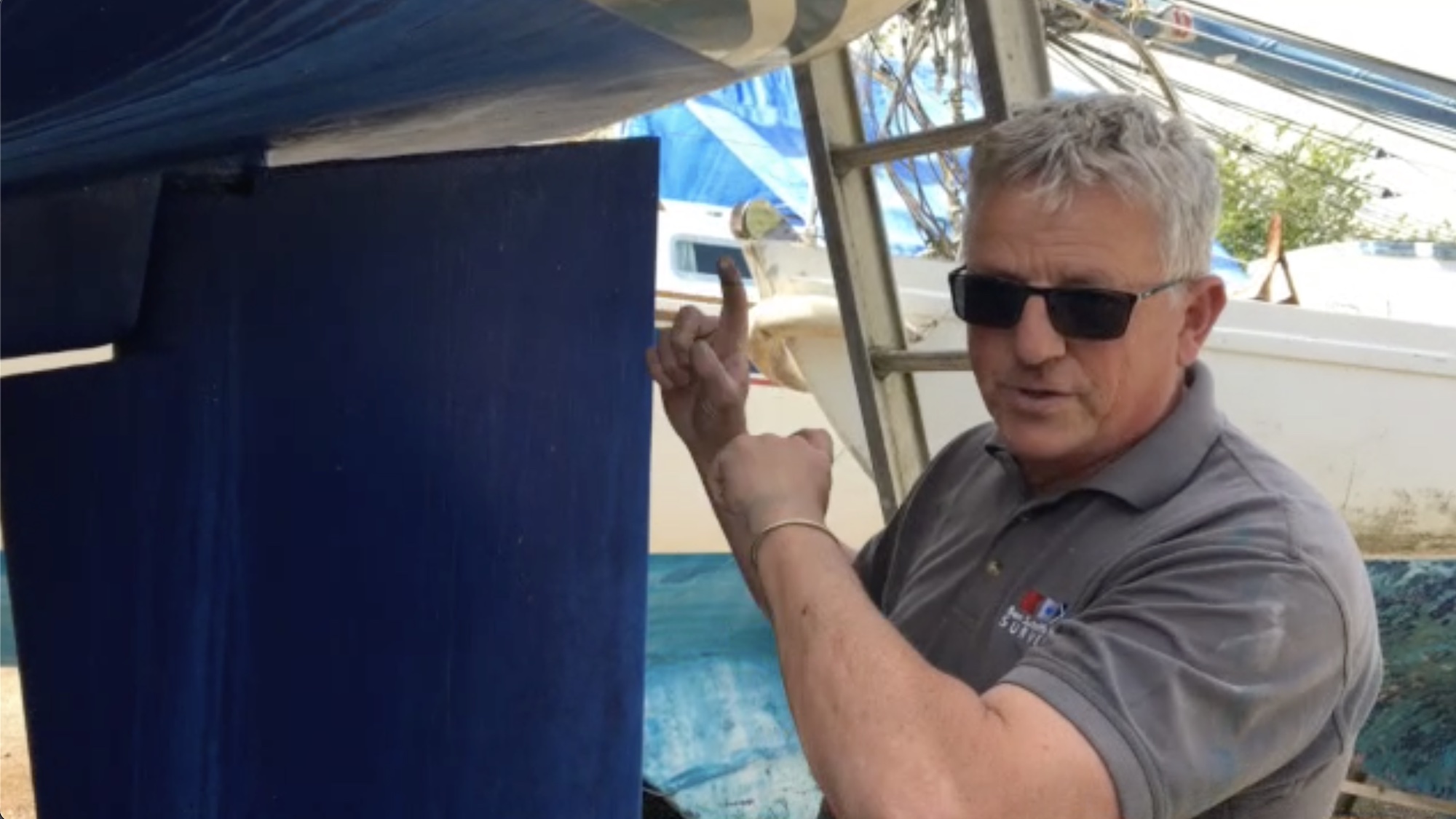
Hitting a submerged object destroyed Mike Gudmunsen’s rudder...so he set about making a new one

The rudder horn on Mike Gudmunsen's yacht had parted company from the palm, leaving the two sides of the palm still bolted to the hull. Credit: Mike Gudmunsen Credit: Mike Gudmunsen
How to build a rudder
The Blackwater estuary above Osea island dries at low water, writes Mike Gudmunsen .
Over the years, wooden jetties, fish traps and even barges have been left to decay at the margins, presenting hazards for the unwary – along with more recent man-made obstacles such as the causeways to Osea and Northey islands.
The spring tides were pretty big and the river had swelled, covering the surrounding salt mashes. Northey island had all but disappeared, apart from the hillock upon which the farm building sits.
I’d enjoyed a good sail around Osea island in my Pegasus and had time for a brew in Goldhanger Creek, but on leaving I became disorientated due to the unusually large expanse of water.
I strayed into an unfamiliar inlet and this was my undoing, as no sooner was I in than I was aground.
Frantic engine manoeuvres and rocking the boat on its keels released the boat, then as I proceeded back towards the main channel there was a resounding crash, the boat stopped dead and the tiller was wrenched from my grasp – I’d hit a submerged object and, whatever it was, it was pretty hard.

Although Mike had previously reinforced the hull around the rudder connection, the grounding still did damage. Credit: Mike Gudmunsen
From the tiller angle and the visible damage to the transom top in way of the upper rudder bearing, something was very wrong.
With minimal steerage, we limped back to our mooring further upriver to contemplate what to do next.
When we hauled the yacht out and inspected the damage, we found the rudder horn had parted company from the palm, leaving the two sides of the palm still bolted to the boat hull .
I’d reinforced the hull around this connection back in 2009 as I was concerned about the potential effects following an impact on the rudder – fortuitously, as it turned out.
Without this additional reinforcement, I suspect the bolts would have been pulled through the GRP and I could have been looking at a total loss.

The remains of the palm. Credit: Mike Gudmunsen
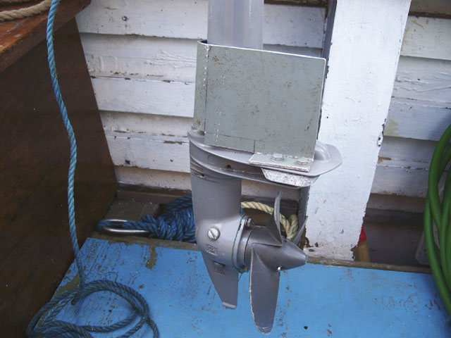
Pegasus yachts have a rather unusual rudder arrangement.
A cast aluminium rudder horn, which forms the leading edge of the rudder for about half its depth, is bolted via a palm to the hull.
At its lower end, a pintle bearing supports the rudder and takes most of the lateral rudder force.
A hollow stainless steel shaft passes through the pintle bearing and terminates above the transom at the tiller head.
Having removed the rudder and unbolted the remaining bits of the palm, I toured various boatyards and marinas hoping to get the rudder repaired.
The builders of Pegasus yachts went out of business many years ago, and it was evident that a replacement cast rudder horn was as rare as hen’s teeth.
So, the only option was to design and fit a spade rudder and move away from the original ‘mariner’-style rudder arrangement.
Designing a new rudder
The helm has always been light and responsive, so I was anxious to maintain those qualities in the new rudder.
I kept the original rudder dimensions and aspect ratio and also the rudder stock position relative to the leading edge.
The original rudder had a chord of 410mm and a maximum thickness of 63mm.
A NACA 0015 aerofoil is very close to these requirements, and I was able to get the section offsets from a site on the internet.
There are important differences between the original ‘mariner’ rudder and the proposed spade rudder .

A cast aluminium rudder horn, which forms the leading edge of the rudder for about half its depth, is bolted via a palm to the hull. Credit: Mike Gudmunsen
The original carried the rudder lateral force via the pintle bearing and into the rudder horn which resists bending at the bolted connection to the hull.
With this arrangement, the rudder stock essentially only carries the rudder torque and, as a consequence, the shaft can be hollow and of modest diameter.
Mine was 38mm diameter with a 3mm wall thickness.
For a spade rudder, the stock itself has to resist bending, shear and torsion, and would clearly need to be a lot thicker and possibly solid.
Calculating the loads on the rudder
A quick trawl on the internet will give numerous references to methods to calculate the forces on a rudder.
They basically all use the blade area (Ar) and the boat speed (V) in knots, together with a few other parameters such as lift coefficient, blade aspect ratio and so on.
For my chosen aerofoil section, I took the design lateral force (Dlf) on the rudder blade, measured in Newtons, to be:
Dlf =100A(V+3)2
The eagle-eyed will notice that lift coefficient and aspect ratio don’t figure in this equation as my 3-knot augmentation of the speed may be considered to compensate for these effects.
The original rudder was 980mm high with a chord of 410mm, giving an area of 0.4018m2.
I took the design speed of my 26ft yacht to be 5 knots. Hence, the lateral force came out to be 2,572N (262kg).
This force acts at the vertical centre of the blade area and, for the NACA section I had selected, at 1⁄3 of the chord from the leading edge.
Continues below…
Do you know your rudders?
Do you know rudders? Boatyards are a great place to get to know different types of keels, rudders and other…
Adding a rudder to a small outboard
Jim Miller suggests a neat way to add a rudder to a Honda BF2.3 outboard motor to aid steering at…

How do you close the gap between the rudder and propeller?
Practical Boat Owner reader David Blackborow is trying to find out the best way to close the gap between the…

Orcas left us rudderless! Yacht couple tell of terrifying ordeal off Spain
Zoe Barlow shares her experience of losing a rudder during sustained attacks by orcas whilst sailing her Sun Odyssey 40…
Having decided on the location of the upper and lower bearings, a simple moment calculation about the top bearing gave the reaction force at the lower bearing (3,983N): likewise, taking moments about the lower bearing gave the reaction force at the upper bearing (1,411N).
By multiplying the lateral rudder force by the distance from the blade centre of area to the lower bearing, the bending moment was determined:
Mb = 0.483m x 2,572 N = 1,242Nm
The torque on the rudder (Mt) was calculated by multiplying the lateral force by the separation between the shaft axis and the centre of pressure.
For my rudder it worked out to be 2,572 x (0.41 x 0.33-0.10) = 91Nm; roughly 10kg.
Interestingly, classification societies set a minimum separation value of 0.12 x chord, which results in a larger torque of 127Nm.
Will the shaft be thick enough?
The rudder shaft would be of 316-grade stainless steel.
Although stainless does not exhibit a yield point, a value of stress for a defined percentage of plastic strain is generally used to represent the nominal yield.
Data from the internet gave a UTS (ultimate tensile strength) of 485N/mm2 and a nominal yield value of 210N/mm2.
The shaft diameter would be limited by the diameter of the existing rudder trunk and also the thickness of the rudder blade.
The rudder trunk had an internal diameter of 50mm.
The rudder blade thickness of 63mm, less two layers of 9mm ply, permits a maximum shaft diameter of 45mm, so it was clear that 45mm would be the largest diameter that could be accommodated in association with these physical limits.
In order to confirm the structural adequacy of the shaft, a few basic calculations needed to be undertaken.
A 45mm-diameter shaft has the following attributes:
The shear area A = π r2 = 1,591mm2 s
Section modulus Z = Ππ d3/32 = 8,946mm3
The torsional constant J = Ππ d4/32 = 402,578mm4
The bending stress in the shaft Mb/Z = 1,242 x 1,000/8,946 = 139N/mm2
The average shear stress F/As = 3,983/1,591 = 2.5 N/mm2.
The torsional stress Mtr/J = 91 x 1,000 x 22.5/402,578 = 5.0 N/mm2
From the results, the dominant stress is the bending stress, and this provides a factor of safety on the nominal yield of 1.5.
The shear and torsional stresses are so small I basically ignored them.
Now I had the shaft diameter, the bearing dimensions could be calculated.

A Delrin spacer ring had to be arranged below the rudder carrier ring in order to take up the clearance. Credit: Mike Gudmunsen
Delrin has a good track record for rudder bearings – it’s easy to machine and has a very low moisture absorption characteristic, particularly when compared with nylon.
Published data on bearing pressures for synthetic bearing material suggests that the design pressures should not exceed 5.5N/mm2.
Based upon the bearing forces of 3,983N and 1,411N, I needed bearing areas of 724mm2 and 256mm2 respectively.
From a purely practical point of view, the bearing depths finally selected were 16mm at the upper bearing and 45mm at the lower bearing, both of which resulted in more than double the minimum areas needed.
The rudder build
The rudder shaft would be subject to some significant machining, and tangs would need to be welded to it in order to transmit the rudder torque to the shaft.
A local marina workshop did the job.
The rudder blade would be laminated from 9mm marine-grade plywood which, after shaping and fairing, was skinned with GRP and finally epoxied.
The bolting location of the original palm provided a convenient location for the new lower bearing.

The bearing plate bolted in place. Credit: Mike Gudmunsen
Using a suitable mandrel as a dummy shaft, I fashioned a cardboard template for the lower bearing plate.
To be honest, I probably made three or four templates before I was satisfied that it was as dimensionally accurate as could possibly be.
A stainless steel tube carrying the lower bearing would need to be welded to this lower bearing plate at precisely the correct angle.
A local engineering shop produced the upper and lower bearing plates, the bearing tube, the Delrin bearings and the rudder carrier ring for me.

The final welding of the bearing tube to the lower bearing plate was carried out by a fellow club member using TIG welding. Credit: Mike Gudmunsen
A steel bush was used as a dummy bearing so the bearing tube could be tack-welded to the lower bearing plate while the rudder shaft was in situ.
Delrin apparently melts at around 160°, so it’s best kept away from the welding process.
Once removed, the final welding of the bearing tube to the lower bearing plate was carried out by a fellow club member using TIG welding.
Even though we left the dummy bearing in place, heat from the welding did cause the bearing tube to warp slightly, so the Delrin bearing had to be adjusted to fit.
The final fitting
The new spade rudder was considerably heavier than the old one and took two of us to offer it up through the rudder trunk, while another assembled the upper bearing components and carrier ring.
Once in place, the lower bearing plate was through-bolted to the hull.
When measuring the shaft length I’d added a 10mm margin to the overall length just in case things didn’t fit as planned.

The final rudder assembly. Credit: Mike Gudmunsen
In the end it proved 8mm over length, so a Delrin spacer ring had to be arranged below the rudder carrier ring in order to take up the clearance.
A club member donated the Delrin and carried out the machining for me.
Completion of the rudder replacement – including producing drawings for the marina and machine shops and calling upon a number of helpful club members to carry out machining and welding – took just over three months.
The whole project proved to be very rewarding and is well within the skills of most practical boat owners.
Enjoyed reading How to build a rudder for your boat?
A subscription to Practical Boat Owner magazine costs around 40% less than the cover price .
Print and digital editions are available through Magazines Direct – where you can also find the latest deals .
PBO is packed with information to help you get the most from boat ownership – whether sail or power.
- Take your DIY skills to the next level with trusted advice on boat maintenance and repairs
- Impartial in-depth gear reviews
- Practical cruising tips for making the most of your time afloat
Follow us on Facebook , Instagram and Twitter
4 Rudder Types for Sailboats

A rudder is an ancient piece of technology that people still use to steer sailboats today. Modern sailboats use many different types of rudders.
If you turn the rudder to the left, the stern will turn right, and vice versa. You can use either a steering wheel or a tiller to move the rudder. Not every type of boat has the same kind of rudder, nor should every boat - different boats need significantly different rudders.
There are several different types of rudders in common use. Sailboats use full keel rudders, spade rudders, outboard rudders, and skeg-mounted rudders, plus variations on each type. What type of rudder is best depends on the shape of the hull and the boat's size.
Table of contents
Different rudder types and their advantages
Full keel rudders.
Many sailboats have a full keel rather than a fin keel, which requires a particular type of rudder. A full keel is the standard type of keel, or flat blade at the bottom of a sailboat. A full keel is designed for stability, not speed - it can keep you safe in rough water.
A generation or two ago, nearly all cruising boats had full keels. However, this is no longer true. Many customers today prefer fin keels, which are designed with speed rather than stability in mind.
A fin keel is smaller than a full keel and shaped differently. Fin keels are more popular today because many sailors today never go far from the coast. If you are near the coast, fin keels are relatively safe.
With a full keel sailboat , the rudder appears to be part of the keel. It is attached with a hinge and looks like a continuation of the keel. There may be a hole between the keel and the rudder, where the propeller is, although not all boats use this design.
What is the advantage of a full keel rudder?
A full keel rudder is strong and protects the boat from harm. A full keel rudder helps a boat survive a storm. Any debris floating by will not snag on a full keel rudder as it will snag on some other rudders.
Do full keel rudders have any disadvantages?
It is harder to move a full rudder than to move other types of rudders. Water flowing by the boat puts a great deal of pressure on a full keel rudder and makes the rudder hard to move. It takes a lot of force to push the rudder against the water moving past the boat.
Spade rudders
Spade rudders are for fin keel boats rather than full keel boats. A spade rudder sticks straight down into the water. A spade rudder can rotate left or right with a rudder post that extends into the hull.
Advantages and disadvantages of spade rudders
The most obvious advantage of the spade rudder is that it can be part of a fin keel boat. A full keel rudder requires a full keel - you could not attach a rudder of this type to another type of boat.
It is also not nearly as difficult to turn a spade rudder as it is to turn a full keel rudder. The water does not put all of its force on one side of the rudder, so it does not take as much force to turn it.
One disadvantage is that debris floating in the water can get caught on a spade rudder. Spade rudders are more delicate than full keel rudders in many ways. Debris can damage a spade rudder.
A spade rudder can also be damaged by rough water. Large waves may exert enough pressure on a spade rudder that it will break. A large wave can bend the rudder post, and after that happens, your rudder becomes useless.
Outboard rudders
An outboard rudder is not part of the boat's hull and is mounted outside of it, at the back of the boat. Usually, an outboard rudder is not hooked up to a steering wheel.
Instead, it is hooked up to a tiller, which is a steering lever. A tiller can take a bit of getting used to if you are used to a steering wheel, but a tiller is not hard to use. Many sailors prefer a tiller, especially for smaller boats.
Advantages and disadvantages of outboard rudders
If an outboard rudder is damaged, it is not likely to damage the rest of the boat. Since there is no rudder post running through the hull, damage to the rudder usually won't mean damage to anything else as well.
You may also be able to remove and fix a damaged outboard rudder while you are still out at sea. There is no way to remove a rudder that is part of the hull and beneath the boat, but a rudder attached to the boat with hinges may be possible to fix at sea.
Outboard rudders are not necessarily weaker than and can be stronger than other types of rudders. The hinges that hold an outboard rudder in place may be stronger than a rudder post.
In some ways, an outboard rudder is worse than either a spade rudder or a full keel rudder. Unlike a full keel rudder, things like rope floating in the water can get caught on an outboard rudder. Objects floating by can also hit and damage an outboard rudder more easily than they can damage a more durable full keel rudder.
Compared to a spade rudder, the outboard rudder is harder to turn. The water pressure will always be on one side of the rudder; this is not always the case with spade rudders.
Skeg mounted rudders
Skeg rudders are both durable and possible to use on fin keel rather than full keel boats. Skeg mounted rudders are more durable than the spade rudders you usually find on fin keel boats.
Skeg mounted rudders have the same disadvantage as full keel rudders and outboard rudders, which is that they require more energy to turn. The water will put all of its pressure on one side of the rudder. Only spade rudders avoid this problem.
Is a tiller better than a wheel?
Either for inexperienced or veteran sailors, a tiller can work better. With a tiller, you will get immediate feedback. If you turn a wheel, the boat won't turn right away, which can confuse or annoy a new sailor.
The tiller should be long enough, as it is harder to turn if it is shorter. In strong winds, you need a long lever to turn your boat without it taking a great deal of strength.
It is easier to turn a wheel than to turn a tiller, as there is more leverage with a steering wheel. Therefore, wheels are better for larger boats; as a tiller is harder to turn with a bigger boat.
A tiller's advantage is that it is more responsive than a wheel, even though it is harder to turn. The boat will start to change direction almost immediately if you use a tiller. In racing, it is normal to use a tiller because you can change direction more quickly.
How does a rudder work?
A rudder works through water pressure. If you turn the rudder, the pressure becomes higher on one side of the rudder than the other. The rudder then moves toward the side with the lower pressure, which causes the boat to change direction.
When a sailboat turns, it pivots around a point near the middle of the boat. Both the stern and the bow move simultaneously, with the middle of the boat not moving. You have to take this into account while sailing, or else you might swing the end of your ship into another boat.
What is the purpose of the keel?
The keel keeps the boat stable. Without a keel sticking down from the boat into the water, it would be easy for the wind to push the boat around. Without a keel, the wind could easily push you sideways and make the ship much harder to control.
A keel is also weighted. The keel is full of ballast, which is weight that keeps the boat from flipping over. Without ballast, a boat would be top-heavy and unsafe.
Keels are usually made out of the same material as the rest of the boat - if the boat is aluminum, the keel will be as well. The ballast is usually lead.
While full keels are better in rough weather in most ways, a fin keel does a better job of preventing the wind from blowing your boat around. Wind can create leeway, which is sideways movement of the boat. Leeway is most likely if you are sailing into the wind.
Do rudders often fail at sea?
Yes, a rudder failure is one of the more common hazards you might encounter at sea. Not every sailboat has a good, durable rudder. The rudders on cheap boats, especially cheap fiberglass boats, can fail.
The rudder pole should neither be too weak nor too strong. If the rudder pole is too weak, it will bend easily. If it is too strong, it may damage the hull rather than bend, which is even more dangerous.
A rudder has a metal framework inside of it. If the framework breaks, the rudder will become unusable. With a cheaper boat, the metal framework may not be welded together properly.
Make sure you buy a sailboat that has a reputation for safety. Don't buy the cheapest boat you can find - look into whether or not the boat is safe to take out to sea.
Related Articles
Daniel Wade
I've personally had thousands of questions about sailing and sailboats over the years. As I learn and experience sailing, and the community, I share the answers that work and make sense to me, here on Life of Sailing.
by this author
Learn About Sailboats
Sailboat Parts
Most Recent

What Does "Sailing By The Lee" Mean?
October 3, 2023

The Best Sailing Schools And Programs: Reviews & Ratings
September 26, 2023
Important Legal Info
Lifeofsailing.com is a participant in the Amazon Services LLC Associates Program, an affiliate advertising program designed to provide a means for sites to earn advertising fees by advertising and linking to Amazon. This site also participates in other affiliate programs and is compensated for referring traffic and business to these companies.
Similar Posts

Affordable Sailboats You Can Build at Home
September 13, 2023

Best Small Sailboat Ornaments
September 12, 2023

Discover the Magic of Hydrofoil Sailboats
December 11, 2023
Popular Posts

Best Liveaboard Catamaran Sailboats
December 28, 2023

Can a Novice Sail Around the World?
Elizabeth O'Malley
June 15, 2022

4 Best Electric Outboard Motors

How Long Did It Take The Vikings To Sail To England?

10 Best Sailboat Brands (And Why)
December 20, 2023

7 Best Places To Liveaboard A Sailboat
Get the best sailing content.
Top Rated Posts
© 2024 Life of Sailing Email: [email protected] Address: 11816 Inwood Rd #3024 Dallas, TX 75244 Disclaimer Privacy Policy
- Classifieds
- Remember Me Forgot Password?
- Boats Sailboats Build Log How to make sailboat rudders and keels in 6999 easy steps
| Page 1 of 11 | 1 |
| . In that thread I show several techniques for casting lead bulbs from simple plaster molds to complex CNC aluminum machining. In this thread I will be doing some similar things, but will not be rehashing some of the intricacies that I have already delved into there, such as the aspects of CAD design and CAM processing. Similarly, I wont be describing EVERY technique available, just the ones I use for my own projects. Hopefully, this will make things a bit easier on me as far as documentation so I am hoping to be able to get things done in 6999 steps instead of 7000 this go around! I also have another build thread going that details the building of the Alioth, a 3d printed IOM. . I will be showing how I make the foils for that boat in this thread. The plan is that these threads will all start to merge together into a finished project as I progress. The bulb and foils threads showing construction techniques for those parts and the boat thread showing the installation. I am keeping these aspects separated because, as in the casting thread, I work on several casting projects. Likewise, I will be doing more than just the Alioth IOM foils in this build thread. Just as in the other threads, I am starting out with a blank slate. I am no expert in making these things and in fact have never made an RC boat rudder or keel fin before. I think this is very important to point out because I want YOU to be able to say to yourself, If this idiot can do it, maybe I can too! That being said, I have some past experience that I am bringing to the table. I have a 25 year background as a professional woodworker and bench jeweler. Nearly three decades in computer art and design work. I have a shop filled with WAY more than the average amount of tools. If there is something in my head that I want made, it is generally gonna get done. One of my key past experiences that will apply in this thread is that I have a history of building with composite construction. I used to be as much into high performance sailplanes as I am currently into sailboats of the same caliber. If you were flying a Taboo GT or XP-5 discus launch glider a decade or so ago, I probably made your fuselage. I was also making DLG carbon tailbooms and made the first fuselages and booms for the Mark Drela XCBD (Cross-country Bubble Dancer). I even built my own CNC 4-axis foam cutter from scratch to make cores for composite sailplane wings and rudders. So, yes I am new to sailboat foils, but will be bringing a lot to the table. I hope to have some fun and do a lot of learning. I also hope for participation and advice from others that have already been down this road. I cannot stress how important it was in my bulb casting thread to stand on the shoulders of others. I will be doing a lot of the same here. I am not an engineer, I just write the manuals. | |
| . | |
| | |
| . | |
| Graham Herbert thinks nature may have figured out a good shape for his IOM foils already. | |
| . | |
| So, there are some definite starting points mentioned above. I have found that there are many roads to take and each builder has their own little twist to add. I am not sure there is a perfect solution, but half the fun is in trying to find one anyway. Someone is screaming at their screen right now. OMG how can you put forth info on designing a rudder for a boat without doing the dozen calculations required for proper this that and the other effect of blah blah blah., etc. Look man, I am not here to present a dissertation. I am here to show you how I built a pretty decent IOM rudder that is probably gonna work out fine. See the previous post for my thoughts how things are going to be OK even if you dont do the math. This is just a prototype whose sole purpose is to verify that I can make a thing that looks about like an IOM rudder to start with. Think about this thread as a vocational tech. class mixed with arts and crafts, not a science class. It is the way I know how to work. Yeah, I took Honors Physics in High School, but even in an Honors class somebody had to get the lowest grade in class and barely pass. Not ashamed to say that in 1991 that person was me! This keel fin is by Gabriel Le Duc. He is doing some nice work in Southern France and I have been following his progress on FB. | |
| . | |
| Rudder drawing in jpg format. | |
| . | |
| Here are experiments from weeks ago showing early 3d print tests leading up to this. Is that a vacuum chuck plate and CNC carved foam cores on the left? Sure is, but that will come later. Right now, we are in printer land! | |
| . | |
| I just want anyone that hasn’t been there before to go check it all out. The doc you want is in “Other” and called Center of Effort Location - fin or rudder. I will also have the PDF for direct download at the bottom of this post. I won’t re-type the instructions, as they are fairly clear on the process. Here is a detail you should pay attention to. Notice the line chosen as the bottom width of the rudder is not at the bottom of the rudder. The rudder tip has a radius to it and Sailsetc. has picked a location about midway through that curve. If you also notice that if you cut the tip off that line, you could about fit that tip piece in the gap near the leading edge that line. This eye-balled line is a bit of a guess. Likewise the location of of the rudder stock axis is said to be placed “no less than 3mm ahead of the center of effort point”. OK, but is there not a “no than Xmm ahead” limit. So, I chose a spot that was 4.5mm ahead of the CE because that as also the location of the thickest point of the rudder airfoil to give maximum room for the rudder stock. When typing up this post I did not want to get complex, but wanted to do more than just throw out the term Center of Effort and devote a post to finding it with no other info at all on why it matters. Luckily, I found some info presented at at a simple level without using any math titled The Physics of Sailing. Take a look here. Mr. Pierce says that CE and CLR represent the centroid of the average forces that are contributed by the foil. So Sailsetc. has provided a way to find that by estimating the location of the centroid (Center of Effort) of the area of the rudder or fin from a 2D view. I used their instructions to find that location with my CAD software. But I also have the ability to push a button and have the software find that exact centroid point using the 3D shape and did so after doing it “manually” and compared locations. Well dangit, they aren’t in the same place. Rhino3D says the 3D volume centroid is about 10.9mm behind and 7mm above the Sailsetc. 2D area centroid position. Hmmm. I proceed to the next step in the instructions which tell you to draw a line from that point to the leading edge and bisect it. I do so and have a minor jaw drop when I see where the midpoint of this line is. If you recall the CE point calculated by the Sailsetc. 2D method places the rudder axis “no less than 3mm” forward from the CE. My computer has taken the complete 3D data of the rudder and found that axis line at this EXACT 3mm offset location. It is kinda cool that you can bypass some advanced math by essentially just saying “move this point ahead about 3mm in the 2D view to make up for the contributions of the 3D volume and you will probably be alright”. | |
| . | |
| Finally, a picture! Here is a mold half, fresh off the printer. | |
| . | |
| This looks like an unfinished sanding job, but this is the point you can stop at. | |
| . | |
| You can also order from Smooth-on, which is where the Amazon stuff ships from anyway, so check to see if you can save buying direct. Make sure your molds are free of any dust, grit, and crud. I mixed up a 15cc batch of epoxy for each mold and did them one at a time so I could keep the epoxy flowing and runny. I only coated the tops of the molds. No reason to do the sides and back. I used a 1/2 shop brush to apply it all over the top. It helps to focus on getting it a bit rubbed in to the plastic. The epoxy may try to pull away from the plastic in a few spots, but working it in just a bit will get it to behave. Make sure there are no puddles, thin spots, or brush hairs (or your hairs) on the surface. Then take several passes down the long axis with your brush, smoothing and evening the coat out while working in full length strokes from tip to the open end of the mold so that excess epoxy is removed as I go. What works nicely at this point is to apply some gentle hot air while holding the mold vertically. This will help surface air bubbles to expand, pop, and self level. It will decrease the viscosity and helps excess epoxy slide down and off the mold. It can also help you smooth out runs and sagging. I have a small heat gun that works great for stuff like this and is fantastic for heat shrink as well. I use it for all kinds of stuff. CAUTION: Do not overdo the heating. You can burn the epoxy or soften the mold. You can cause curing to begin immediately. You can cause tiny bubbles become huge, hardened lumps. What you can get away with will depend on your heat source. Test out your technique on a sample print before you coat the molds. I have quickly flashed a propane torch over epoxy for a second or two just to pop bubbles. I have also spent a minute of time working on flattening a run with a low temp heat/air source. Experiment until you have some experience. Now stand your mold vertically and leaned back a bit so no epoxy accumulates at the open base. It is fine for it to run off the end and drip freely. You can pop the runs off the mold base with a chisel later. Dont be too disturbed with how it looks. My pictures below will show you several mistakes, such as a trapped hair in the black mold. Also, hardened bubbles because it was hot as Hades in my shop that day and the epoxy was bit too stiff by the time I remembered I needed the hot air gun. I even had epoxy build up the open end because I forgot to tip the molds back once I had my area cleaned up for the day. The first coat of this stuff almost always looks like poo, even on my best days. It will come out fine in the end. Looks ugly? Yep. No worries. It will get taken care of. First coat is on. Not pretty, but it is even. | |
| . | |
| This is the black mold from the previous post after being having the first coat sanded, but before the 2nd epoxy coat. I told you it was going to come together! Donât sweat those scratches. Coat #2 will manage them. | |
| RCGroups Message | |
| Quick Reply | |
| The following errors occurred with your submission | |
| Thread Tools | |
| Similar Threads | |||||
| Category | Thread | Thread Starter | Forum | Replies | Last Post |
| Discussion | MtnGoat | Life, The Universe, and Politics | 50 | Aug 03, 2022 06:31 PM | |
| Build Log | will_newton | Sailboats | 89 | May 22, 2022 04:43 AM | |
| Question | BerkannY | Ornithopters | 5 | Apr 08, 2022 04:38 PM | |
| Discussion | spencer911 | Sailboats | 12 | Oct 20, 2015 02:03 PM | |
| Paul Penney | Scratchbuilt Indoor and Micro Models | 209 | Apr 20, 2009 03:42 PM | ||
- Electric Flight
- Advertising
- Our Sponsors
- Review Policies
- Terms of Service
- Privacy Policy
- Site History
- Mark Forums Read
- Member Search
- Upcoming Articles
- Do Not Sell My Data
- Manage Consent
- Back to Top
How To Make A Rudder For A Sailboat?
- REPAIRS AND MAINTENANCE
Sailboats are propelled through the water by wind power, and a rudder accomplishes steering. It is a flat piece of wood or metal that hangs in the water and is fastened to the back of the boat. A tiller connected to the rudder controls its side-to-side movement.
A crucial skill that releases your sailboat’s full potential is making a rudder. Start by carefully choosing the right materials, such as wood or fiberglass, based on your preferences and financial constraints.
Next, meticulously design the rudder’s shape to ensure optimal hydrodynamics. With precision, cut the materials according to your design, shaping them into the perfect rudder. But that’s not all; we have more valuable steps ahead to enhance your rudder’s performance.
Ready to take control of your sailboat like a seasoned captain? Let’s delve into the detailed process of making your very own rudder, turning your sailing dreams into reality!
Read Related Articles:
- How Often Do Sailboats Get Struck By Lightning?
- How To Hang A Hammock On A Sailboat
What Materials Do You Need to Make a Rudder?
The following supplies are necessary to launch this ship if you’re prepared to learn the technique of building sailboat rudders. Let’s take a step-by-step look at how to create this nautical beauty and then give you the lowdown on what you’ll need.
Perfect Wood
When choosing the right wood for your sailboat rudder, durability and water resistance are key. Two types of wood are excellent choices: marine-grade plywood and hardwoods like oak or mahogany.
Marine-grade plywood boasts superior resistance to water and decay, making it an ideal option for exposed marine environments. On the other hand, hardwoods bring a touch of elegance and strength to your rudder, but they may require additional waterproofing measures.
Plywood Thickness – Striking the Right Balance
The thickness of the plywood used for your rudder is a crucial consideration. While thicker plywood tends to be more durable, it can also add unnecessary weight to your sailboat.
In general, a thickness of ¾-inch plywood strikes the appropriate mix between strength and weight, ensuring that your rudder stays functional and maneuverable.
Your sailboat’s size and weight will determine whether you can use somewhat thinner plywood without compromising strength.
Get yourself a trusty jigsaw, a powerful drill, and a router. Oh, and don’t forget some sturdy clamps because you’re going to need them to hold things together while the magic happens.
Glue it All Together:
Time to get sticky! You’re going to need some marine-grade epoxy or a heavy-duty adhesive to bond those plywood layers together. Trust me; you want to go heavy on that glue – no room for gaps in this masterpiece!
Gudgeons and Hinges:
Now, we can’t forget the rudder’s backbone – the gudgeons and hinges. Look for some stainless steel gudgeons, my friends. They’re tough, they’re reliable, and they can handle the rough waters like a champ.
Pivot Bolts:
Ah, yes, the pivot bolts. Get yourself some stainless steel bolts because you want them to hold up against the salty sea spray. You don’t want those rusty bolts seizing up when you’re out on the water, do you?
The Sturdy Tiller:
Don’t forget about the tiller! Craft it from solid wood, and ensure it’s long enough to give you proper steering control. You want to feel that connection with your rudder, am I right?
Eye Bolts and Cleats:
We need some eye bolts and cleats to keep things in place. These little guys will make your life much easier when raising and lowering the rudder. Just the way we like it: simple and effective.
How Do You Design and Shape the Rudder Blade?
Now that we have gathered our materials, it’s time to delve into the art of designing and shaping the sailboat rudder blade. A well-crafted rudder not only ensures smooth steering but also enhances the overall performance of your vessel.
The Art of Rudder Blade Design
Designing your rudder blade is akin to crafting a work of art. The key considerations are the blade’s size, shape, and foil design. First, determine the ideal size of the blade based on the dimensions of your sailboat. A larger sailboat will require a proportionately larger rudder blade to ensure effective steering control.
Next, the shape of the rudder blade plays a crucial role in its hydrodynamics. A balanced and streamlined shape will reduce drag and enable smooth maneuvering. Many sailors opt for a symmetrical foil design, similar to an airplane wing, which ensures equal pressure on both sides of the blade for optimal performance.
Shaping the Rudder Blade – From Plywood to Foil
Now, let’s roll up our sleeves and bring our rudder blade design to life! Start by tracing your desired shape onto the plywood using a template or drawing your unique design. Precision is key here, as even small deviations can impact the rudder’s functionality.
With the outline in place, carefully cut the plywood along the traced lines using a sharp saw. For the finest precision, a jigsaw or bandsaw is ideal. As you make each cut, envision the graceful motion of the blade gliding through the water, guided by your craftsmanship.
Perfecting the Foil Shape – Hydrodynamics at Play
Ah, the magic of hydrodynamics! Now that we have the basic shape of the rudder blade let’s fine-tune it to achieve the perfect foil shape. The foil shape, similar to an airplane wing, generates lift and minimizes drag as the water flows past it.
For a symmetrical foil shape, gently taper the front and back edges of the blade to create a graceful curve. Imagine the water caressing these contours, guiding your sailboat effortlessly across the waves.
Remember, precision is paramount in achieving an efficient foil shape. Use a sander to smooth the edges, refining the curves and angles until you achieve hydrodynamic perfection. Remember that even subtle adjustments can significantly affect your sailboat’s performance.
How to Assemble the Rudder Gudgeons and Hinges?
We’ll now get started on the rudder assembly process and learn how to put the hinges and gudgeons—two crucial parts—together. These essential components not only guarantee the correct operation of your sailboat’s rudder, but they also offer the flexibility required for easy navigation.
Understanding the Role of Rudder Gudgeons
- Gudgeons and Pintles : Rudder gudgeons are small metal brackets or plates attached to the transom of your sailboat. They serve as the pivot point for your rudder, allowing it to swing smoothly. Corresponding to the gudgeons are pintles, which are mounted on the rudder’s sides and fit into the gudgeons to form the hinge mechanism.
- Material Matters: Rudder gudgeons are typically made from marine-grade stainless steel or other corrosion-resistant materials. The robustness of these components ensures their longevity in the harsh marine environment.
Assembling the Rudder Gudgeons and Hinges
With a clear understanding of the gudgeons’ role, it’s time to assemble these vital components:
- Preparing the Transom: Begin by positioning the rudder gudgeons on the transom’s surface. Ensure that they are aligned and centered to create a stable hinge point for your rudder.
- Marking and Drilling: Using the gudgeons as guides, mark the spots for the screw holes on the transom. Carefully drill pilot holes to avoid any splitting or damage to the wood.
- Mounting the Gudgeons: With the pilot holes in place, attach the rudder gudgeons firmly to the transom using stainless steel screws. Ensure a snug fit to maintain stability during rudder operation.
- Fitting the Rudder: With the gudgeons securely mounted, position your rudder with pintles in place. Ensure that the pintles fit smoothly into the gudgeons, allowing for easy movement.
- Securing the Rudder: After testing the movement of the rudder, secure it in place with retaining pins or bolts. This prevents the rudder from accidentally dislodging during your sailing adventures.
Fine-Tuning the Hinge Mechanism
To achieve flawless rudder movement, fine-tuning the hinge mechanism is crucial:
- Lubrication: Applying marine-grade lubricant to the gudgeons and pintles enhances the smoothness of the hinge action, reducing friction and ensuring easy steering.
- Eliminating Play: Check for any unwanted play or wobbling in the rudder movement. Adjust the gudgeons or pintles if needed to achieve a snug fit without excess movement.
What’s the Process of Making the Tiller?
Ahoy, shipbuilders! As we continue our voyage into sailboat construction, it’s time to focus on the essential tiller – the steering companion of our rudder. Making the perfect tiller ensures smooth navigation and precise control. So, let’s set our sights on the art of tiller craftsmanship!
Selecting the Perfect Tiller Material
Before we set our hands to work, let’s consider the materials for your tiller:
- Wood: Wooden tillers are a popular choice, offering a classic and traditional look. Hardwoods like oak, teak, or mahogany are excellent options due to their strength and resistance to water damage.
- Composites: For a modern touch, composites like fiberglass or carbon fiber provide a lightweight and durable alternative.
- Length Matters: Choose a tiller length that allows for easy maneuvering while providing enough leverage for precise steering control.
Crafting the Tiller Handle
- Shaping the Handle: Start with a rectangular piece of wood or composite and shape it into a comfortable grip. Rounding the edges and creating ergonomic contours enhances handling and reduces hand fatigue.
- Pivoting Mechanism: If you desire a tiller that pivots for ease of navigation, consider attaching a pivot bolt to the tiller handle’s base. This allows the tiller to lift easily when needed.
Reinforcing the Tiller for Strength
- Multiple Layers: If using wood, glue multiple layers of plywood together to achieve the desired thickness. This ensures your tiller can withstand the forces of steering.
- Bolt or Eye Loops: Strengthen the pivot point by inserting a bolt or eye loop through the tiller handle. This provides a secure connection to the rudder mechanism.
- Tapering the Tiller: Taper the tiller towards the rudder end, reducing its width for a sleek and aesthetically pleasing look.
Finishing Touches
- Varnishing: Apply marine-grade varnish to protect the tiller from water damage and give it a glossy finish.
- Grip Enhancement: Consider adding a non-slip grip surface, such as rubber or leather, to the tiller handle for improved control in wet conditions.
- Customization: Add a personal touch by carving your sailboat’s name or a unique design onto the tiller.
How to Install the Rudder on the Sailboat?
As we approach the final leg of our sailboat construction, it’s time to install the rudder – the heart and soul of our steering mechanism. A well-executed rudder installation ensures smooth sailing and ultimate control.
Choosing the Right Rudder Location
Before we dive into the installation, let’s consider the ideal location for your rudder:
- Transom Position: The transom, or the rear part of the boat, is the most common location for rudder installation. Ensure that the rudder gudgeons are aligned with the pintles on the rudder blade for a secure and stable fit.
- Clear Path: Make sure there is enough clearance around the rudder to allow for smooth movement without any obstructions.
- Balance and Control: Position the rudder in a way that provides optimal balance to your sailboat and allows for effortless control during navigation.
Mounting the Rudder Gudgeons
- Precise Measurements: Use a level and measuring tape to ensure the gudgeons are mounted at the correct height and alignment on the transom.
- Marking and Drilling: Carefully mark the spots for the screw holes and drill pilot holes to prevent any damage to the transom.
- Securing the Gudgeons: Attach the rudder gudgeons firmly to the transom using stainless steel screws. Double-check their alignment to ensure a proper hinge mechanism.
Fitting the Rudder in Place
- Pintle Alignment: Carefully insert the pintles on the rudder blade into the gudgeons on the transom. Ensure a smooth and snug fit to allow for effortless rudder movement.
- Testing the Rudder: Move the rudder back and forth to test its range of motion. Verify that it swings smoothly and without any binding or resistance.
- Securing the Rudder: Once satisfied with the rudder’s movement, secure it in place by inserting retaining pins or bolts through the pintles and gudgeons.
Waterproofing and Final Checks
Before setting sail, let’s take some additional steps to protect your rudder and ensure a safe voyage:
- Waterproofing: Apply marine-grade sealant or epoxy to the areas around the gudgeons and pintles to prevent water from seeping into the transom.
- Quality Checks: Perform a thorough inspection of the rudder installation, checking for any loose fittings or potential points of concern.
- Rudder Lines : If your rudder design includes lines for raising and lowering, make sure they are properly attached and secured to the tiller and rudder.
How Does a Rudder Work on a Sailboat?
A sailboat rudder is a vertical, blade-like appendage mounted either on the transom (the flat surface of the stern) or under the boat. It operates by deflecting water flow: when the helmsman turns the rudder, the water strikes it with increased force on one side and decreased force on the other.
The rudder moves toward lower pressure, causing the boat to turn. During turns, the boat pivots around a point close to its middle, changing direction as the stern and bow move in opposite directions.
A tiller, a wooden or aluminum pole affixed to the top of the rudder on smaller sailboats, is often used to control the rudder. Hydraulic, steam or electrical machinery turns the rudder on larger vessels.
Why Is the Rudder So Important?
The rudder is crucial for steering and changing the direction of a sailboat. It is mounted at the stern and controlled by the helm or tiller. When the helmsman turns the wheel or tiller, the rudder moves to either side, which turns the boat’s bow left or right.
This directional control is essential for navigating the water, avoiding obstacles, and maintaining stability during sailing. A functional rudder ensures safe and efficient maneuvering of the sailboat, making it an indispensable component of any sailing vessel.
What Are the Different Types of Rudders for Sailboats?
There are four types of rudders for sailboats: Full Rudder, outboard Rudder, Spade Rudder, and Skeg-Mounted Rudder.
Full Keel Rudders:
Some sailboats boast a full keel rudder, which extends along the entire length of the boat’s bottom. These rudders offer stability and protection, making them ideal for rough waters. Back in the day, many cruising boats rocked the full keel, but times have changed, and modern sailors tend to favor speedier fin keels.
Spade Rudders:
Spade rudders are like the cool cats of the sailing world, often found on center-console boats. They’re separate from the keel and turn easily, thanks to water flow rushing against both fore and aft edges. Less wet area means they’re fast and perfect for modern sailboat designs.
Skeg-Mounted Rudders:
If safety and performance are your jam, the skeg rudder is your go-to choice. Popular on current production boats, the skeg rudder combines the best of both worlds. It’s modern, stable, and performs like a champ.
Outboard Rudders:
These rudders are the real deal when it comes to simplicity. They can be unbalanced, balanced, or semi-balanced, and their location behind the hull determines whether they’re inboard or outboard.
Frequently Asked Questions
- What Is the Best Material for the Rudder?
A boat’s rudder is a steering device. To withstand the power of the water, it is typically composed of sturdy and rigid material like metal. The best material for a rudder depends on where it will be used. If it is used in salt water, it must resist corrosion. When used in freshwater, it must be resistant to sunlight degradation.
- What Type of Bearing Holds a Rudder?
Two bearings commonly hold a rudder in place: roller and journal. Roller bearings are composed of small cylindrical rollers arranged perpendicular to the axis of the shaft. On the other hand, journal bearings consist of a smooth inner surface on which the shaft rotates.
- Do Motor Boats Have Rudders?
Rudders are a feature of motor boats used to steer the vessel. It is attached to the back of the boat and regulates the direction.
- What Happens If the Rudder Is Too Big?
When the rudder is overly large, the boat may veer off course. The rudder is what steers the boat; thus, if it is excessively large, it could be challenging to manage the boat’s direction. A boat might become slower if its rudder is excessively large and causes drag.
- How Much Is a New Rudder?
The kind, size, and material all affect the price of a new rudder. A sailboat’s rudder can usually range between $200 and $500 for small sailboats and between $800 and $2,000 for bigger vessels. It’s best to consult with a marine supplier or boatyard for precise pricing.
Congratulations, skilled shipwrights! You’ve navigated the intricate waters of sailboat rudder construction with finesse. From selecting the right materials to crafting the perfect foil shape, you’ve honed your craftsmanship like seasoned sailors. With the rudder securely mounted and tested, your sailboat is ready to embrace the vast horizon.
As you set sail on new adventures, may your well-crafted rudder be your faithful companion, steering you toward endless nautical wonders. Embrace the sea’s call and embark on a journey filled with the wind’s whispers and the thrill of the open ocean. Smooth sailing awaits you! Bon voyage!

Jack K. Pride
Jack K. Pride is an accomplished author and a prominent figure in the boating community. With a passion for boats and a deep understanding of the maritime industry, he has been sharing his expertise through his compelling articles on OutedWeb.com.
Known for his insightful and informative writing style, Jack's articles provide valuable insights, tips, and knowledge to boat enthusiasts worldwide. His dedication to the subject matter and commitment to delivering high-quality content makes him a trusted voice in the boating world.
Leave a Reply Cancel Reply
Your email address will not be published. Required fields are marked *
Name *
Email *
Add Comment *
Save my name, email, and website in this browser for the next time I comment.
Post Comment
- New Sailboats
- Sailboats 21-30ft
- Sailboats 31-35ft
- Sailboats 36-40ft
- Sailboats Over 40ft
- Sailboats Under 21feet
- used_sailboats
- Apps and Computer Programs
- Communications
- Fishfinders
- Handheld Electronics
- Plotters MFDS Rradar
- Wind, Speed & Depth Instruments
- Anchoring Mooring
- Running Rigging
- Sails Canvas
- Standing Rigging
- Diesel Engines
- Off Grid Energy
- Cleaning Waxing
- DIY Projects
- Repair, Tools & Materials
- Spare Parts
- Tools & Gadgets
- Cabin Comfort
- Ventilation
- Footwear Apparel
- Foul Weather Gear
- Mailport & PS Advisor
- Inside Practical Sailor Blog
- Activate My Web Access
- Reset Password
- Customer Service

- Free Newsletter
Catalina 270 vs. The Beneteau First 265 Used Boat Match-Up

Ericson 41 Used Boat Review

Mason 33 Used Boat Review

Beneteau 311, Catalina 310 and Hunter 326 Used Boat Comparison

Tips From A First “Sail” on the ICW

Tillerpilot Tips and Safety Cautions

Best Crimpers and Strippers for Fixing Marine Electrical Connectors

Thinking Through a Solar Power Installation

Polyester vs. Nylon Rode

Getting the Most Out of Older Sails

How (Not) to Tie Your Boat to a Dock

Stopping Mainsheet Twist
Fuel Lift Pump: Easy DIY Diesel Fuel System Diagnostic and Repair

Ensuring Safe Shorepower

Sinking? Check Your Stuffing Box

The Rain Catcher’s Guide

What Do You Do With Old Fiberglass Boats?

Boat Repairs for the Technically Illiterate

Boat Maintenance for the Technically Illiterate: Part 1

Whats the Best Way to Restore Clear Plastic Windows?

Giving Bugs the Big Goodbye

Galley Gadgets for the Cruising Sailor

Those Extras you Don’t Need But Love to Have

What’s the Best Sunscreen?

UV Clothing: Is It Worth the Hype?

Preparing Yourself for Solo Sailing

How to Select Crew for a Passage or Delivery

R. Tucker Thompson Tall Ship Youth Voyage

On Watch: This 60-Year-Old Hinckley Pilot 35 is Also a Working…

On Watch: America’s Cup

On Watch: All Eyes on Europe Sail Racing

Dear Readers
- Systems & Propulsion
Rudder Mods for Low-speed Docking

A ny sailor who has tried to wrestle a full-keel ketch with a barn-door rudder into a tight slip has probably wondered if they could modify the rudder to improve low-speed maneuvering without slowing the boat down under sail. As it turns out, there are several rudder design tweaks designed to improve control on ships, large working boats, and trawlers, but few have been implemented widely in the sailing world.
Most sailors have a general understanding of how a rudder works, because the concepts of lift and drag that apply to sail trim and keels also apply to what happens underwater with respect to rudder trim. The rudder’s angle in relation to the flow of water as the boat moves through the water is its angle of attack. When this angle changes, it creates a low-pressure zone on one side of the rudder that “lifts” the rudder forward toward that zone. On the other side of the rudder is drag, the enemy of lift.
At low speed, or when making sharp turns—two essential features of any docking exercise—the lift is so anemic that drag can cause the rudder to stall, and the skipper must rely on other forces such as prop walk (forces generated by the propeller’s rotation) or prop wash to squeeze the boat into its slip. For responsive steering when docking, you want a rudder profile that has a healthy lift-to-drag ratio at low speed. This is not possible using the most popular rudder designs, which are based on foils developed by the National Advisory Committee for Aeronautics (NACA). The NACA foil shapes, designed to provide optimal lift-drag ratios for aircraft operating at higher speeds when flying a relatively straight line, are not the best suited to making sharp turns at slow speeds (see illustration, page 20).
Our dive into the world of rudder designs for low-speed maneuvering was triggered by questions from a reader who was frustrated with the close quarter maneuvering capabilities of his full-keel sailboat. He was happy with the boat’s performance when sailing, but under power, and particularly at low speed, the boat simply would not turn. He had read that if he attached a 90-degree angle iron on each side of his rudder’s trailing edge, his rudder would be far more effective.
Since a modification that adds drag at the trailing edge seems to go against the conventional wisdom that a knife-like trailing edge is best for sailboats (see “Building a Faster Rudder,” PS June 2021), he was baffled to say the least. We were curious, too. Are there unconventional rudder profiles—at least in the world of sailing—that might be a better fit for a boat like his? When docking in close quarters, an auxiliary-powered sailboat effectively behaves as a powerboat, so it is worth looking at what rudder modifications have helped trawlers, fishing boats, or commercial ships tighten their turning radius.
SAILBOAT RUDDERS
Sailboat rudders serve as both a control device for steering and lateral plane to develop lift. When sailing straight, or nearly so, the rudder operates at a relatively steady, low angle of attack. The low angle is nowhere near one that would interrupt the flow of water and cause the rudder to stall.
On a well-designed sailboat in good trim, weather helm is about 2-5 degrees. This is the rudder angle required to steer a straight course while reaching. But that’s just part of the equation. Like the keel, the rudder is impacted by leeway, slipping about 5- to-10 degrees in relation to the course steered. This means the rudder’s actual angle of attack through the water is about 7-to-15 degrees.
An efficient NACA rudder profile will provide a favorable lift-to-drag ratio up to an angle of attack of about 16-to-20 degrees, so you have limited “wiggle-room” before the rudder will begin to stall.
Because a sailboat rudder needs to provide lift at relatively low speeds, it needs a relatively large surface area and a foil shape with a high aspect ratio. Aspect ratio is the ratio between the chord—the straight-line distance between the leading and trailing edges of the foil—and the foil’s span, or length (depth in the case of a sailboat rudder).
These narrow and deep NACA-based rudder shapes are designed for maximum efficiency going to windward. They provide adequate maneuverability under sail but aren’t very efficient under power. Racing designs exacerbate low-speed steering problems by putting the rudder as far from the prop as possible to minimize turbulence at the rudder. This makes it virtually impossible to nudge the stern to port or starboard by redirecting propwash with a sharply turned rudder a common tactic during docking maneuvers.

POWERBOAT RUDDERS
The rudder on an inboard-powered trawler or cabin-cruiser by comparison, operates in the high velocity slipstream of the propeller. It is not asked to resist the steady sideways pressure of the wind, only to provide turning force. Any additional rudder area hanging below the prop’s stream only adds drag (and draft) with very little benefit. The profile must be low drag, and as a result, many powerboat rudders are nothing more than a flat plate welded to a shaft with whatever reinforcement is required. This provides acceptable docking performance so long as the timely bursts of power are applied at the right rudder angle. Larger ships, with a lower power-to-mass ratio, require some additional help.
SHIP RUDDERS
Ocean going ships focus on straight-line efficiency. They are assisted by a harbor tug when docking. They use rudder sections like those of sailboats for slightly improved lift-to-drag ratios, but the rudder remains small. However, some ships, including tugs, coastal freighters, and barges, require greater maneuverability. When navigating in constrained waterways, these ships and work boats spend a great deal of time with the helm turned at high angles.
As a result, naval architects have developed different rudder sections that will operate effectively at much higher angles than traditional NACA sections we see on sailboat rudders. These convex shapes are referred to as “fishtail sections”. Examples of fishtail rudder designs are the Schilling and Thistle rudders (proprietary foil sections named by their designers), which can reduce the turning circle of a boat by as much as 50 percent. Some examples of these low-speed designs are shown alongside conventional sailboat rudder (NACA) profiles in the illustration.
If you have a spade rudder located a few feet away from the prop, you won’t gain anything with a fishtail section. Effective use of prop-wash—along with an experienced hand at the helm—should be enough to get you in and out of a slip. However, if you are the owner of a shoal draft boat with a short rudder, a full-keel cruising boat, or a motorsailer, and have been kept awake by visions of bow thrusters dancing in your head, read on.

LOW SPEED STEERING UNDER SAIL
At low angles of attack, water flows relatively evenly around both sides of the rudder, creating minimum drag. This streamline, also called laminar flow, remains “attached” to the rudder’s surface. Any change in relative speed or direction that interrupts this flow can cause the rudder to stall.
When a rudder stalls, the water on the low-pressure side is no longer deflected effectively, creating a separation bubble that reduces lift on the low-pressure side. At the same time, drag on the high-pressure side of the rudder continues to rise. As result, the low-pressure side of the rudder’s trailing edge becomes less important, because it is within the eddy zone (separation bubble, see adjacent illustration). Since there is very little water flow over this surface, it does not create much drag. Only the flap on the high-pressure side sees flow and generates drag. We’ll come back to the latter point, but it should be apparent that sailboat rudders cannot operate in the stalled region; the drag is too high for windward work, and the lift is too low for high-speed corrections in big waves.
When maneuvering under power at low speed we need more lift, so drag doesn’t really matter. To overcome any drag, we can just use more throttle. Airliners use massive flaps when landing. The drag is horrendous, but since they are descending and trying to reduce speed, they have plenty of reserve power to overcome drag. The tradeoff is worth it. During take-off, when they have less power to spare, they use zero flaps (and sometimes high-lift devices called slats on the wings’ leading edge).

In search of new symmetrical shapes with the same high lift characteristics as an asymmetrical airplane wing, ship designers began experimenting. In fact, some ships use rudders with flapped trailing edges, like airplane flaps, but simpler. After much trial and error, simpler, non-articulating sections, referred to as fishtails, were found to have many of the same beneficial characteristics as a jet wing.
As a result of this research, a series of foils were developed in Germany by the Hamburgische Schiffbau Versuchsanstal (Hamburg Model Ship Basin) and the Institute für Schiffbau (Institute for Ship Building). Named after their place of origin, these shapes were designated HSVA shapes and HVS shapes. A variety of proprietary wedges and fishtails grew from there.
When a vessel is steering a straight path and the rudder has a low angle of attack, HSVA and HVS shapes create slightly more drag than NACA profiles of equal lift. However, they delay stall and create more lift at higher angles. Although the wedge or flap slightly increases drag, once the foil stalls, this drag is minimized because it is in the separation bubble.
As shown in the example foils (see Figure 1), the “fishtail” is a wedge-like section at the trailing edge. Generally, the maximum thickness of wedge will be no more than the maximum thickness of the rudder. The ideal thickness of a sailboat rudder is about 20 percent of the chord—the distance between the leading and trailing edge measured parallel to the normal laminar flow (see Figure 2). Ideally, a fishtail rudder will be based on a concave HSVA or HVS section, but simply adding a wedge at the trailing edge of NACA profile or a flat plate has proven to be a cost-effective way to achieve similar performance.

ADDING END PLATES
Another feature of high-lift rudders are endplates. Just as the name implies, these are plates at the top and bottom “ends” of the rudder. Their purpose is to help direct laminar flow over the rudder, by reducing loss of flow at the rudder tips (known as tip loss).
You don’t often see endplates on sailboat rudders or keels because they can create a lot of turbulence and drag. In addition, the deep, narrow (high-aspect) rudder of a sailboat will suffer much less tip loss than a broad shallow (low-aspect) one found on most powerboats. Finally, the narrow gap between the top of the rudder and the flat stern section of a racing sailboat effectively creates an endplate at the top of the rudder, eliminating the need for one there.
Endplates will be more appealing to owners of motorsailers, heavy-displacement sailboats with barn door rudders, or other large auxiliary sailboat designs that can create headaches during docking. On these boats, the additional drag under sail may be worth better maneuverability under power.
These “endplates” on a sailboat rudder don’t have to be at the ends of the rudder as they are on a powerboat; they can be at the top and bottom of the rudder’s prop wash zone to help direct laminar flow and improve rudder lift under power. On a motorsailer, to make full use of the prop thrust, the distance between the end plates should about 120 percent of the prop diameter. The plate width should be about 120 percent of the maximum thickness of the foil, or, in the case of a thin, flat rudder, 20 percent of the chord.

OTHER CONSIDERATIONS
Adding endplates or a fishtail can have some unintended consequences. For example, it will move the rudder’s center of effort aft, making it harder to steer. The change is most pronounced at low speeds with the helm well over, but forces are low, so this is not typically a problem. At higher speeds, the difference will be more noticeable, and this is something to look for during a sea-trial before you commit to a permanent change.
To get the maximum benefit of a fishtail rudder with or without endplates, one could also experiment with moving the end stops, which limit the maximum angle you can turn the rudder to either side—although we’d be very careful with this. Rudder end stops generally limit rudder angle to 35 degrees, the maximum angle at which conventional rudder designs are effective.
A fishtail design will work beyond this limit, up to 45 degrees, potentially reducing turning radius by up to 50 percent at speeds of 2-to-4 knots. However, increasing rudder angle will also increase loads on the rudder stock and rudder bearing when the boat is in reverse or, more seriously, getting tossed backward by a wave in extreme conditions. Although we have few qualms about experimenting with end plates and wedges, we wouldn’t mess with rudder stops on an offshore cruising boat without some professional guidance from an engineer or naval architect.

While this seems like a lot of effort to make docking easier, having control at low speed can be beneficial at sea, as well. You will have better control when powering in adverse weather, slowing down to the minimum speed that allows for control—steerage speed—which can help in heavy weather.
This report is not advocating for rudder redesign on a sailboat that steers adequately at low speeds under power. Nor should it be construed as surefire way to fix steering problems on problem boats, although we’re optimistic that it will help. Based on solid evidence from the world of trawlers, working boats and ships, it is a concept that deserves more study. We have not yet been able to test fishtail rudders on our own sailboats, but many vessels, both commercial and recreational—have added fishtails with positive results. We’d be interested in hearing from sailors who might have experimented with either.
As for endplates, we strongly believe that they are smart idea on trawler rudders; the only downside is that it can snag weed. To prevent this, we would leave the forward portion of the plate flush with the leading edge of the rudder and then rake it in a streamlined form as it extends aft. Shallow-draft motorsailers with trawler-like rudders could also benefit from streamlined endplates. As mentioned, the endplates don’t have to be at the rudder tips, they could be positioned to maximize prop wash.
Adding a fishtail becomes more complicated. What angle works best? How will it impact rudder balance? The HVSA sections are a good starting point when conceptualizing fishtail sections. Although adding a simple 90-degree angle at the trailing edge is common, naval architect Dave Gerr, the author of several books on yacht design and engineering, suggests starting with a metal plate that can be adjusted to alter its angle.
If you want to experiment, you could attach a stainless-steel sheet metal strips to each side of the rudder. The metal would be bent at an angle that mimics the shape of your preferred fishtail. During sea trials, you can adjust the angle until you find one that works. If you are using stainless-steel bolts or screws to fasten the sheet metal, you will want to be extremely careful about not allowing any water into the rudder laminate or foam core. Seal the core with epoxy as you would when fastening deck hardware or fasten the angle using high-strength adhesive.
If the angle doesn’t seem to help, you can take it off, fill the holes, and master the art of using spring lines to squeeze your boat in and out of its slip on windy days. If your improvised fishtail does improve low-speed steering, consider shaping a more permanent section that can be bonded to the original rudder—or building a new rudder to the improved design. If you are also adding endplates, the fishtail sections do not need to be mechanically attached to the endplates, but they should be very close.
Full keel sailboats are never going to turn on a dime; they like to go straight. But there is plenty of evidence that a fishtail section, such as the concave IFS61, located just aft of the prop, could improve low-speed performance. We doubt this fishtail section located directly behind a 3-to-4 blade fixed prop will have any negative effect on sailing—the flow is turbulent behind the prop anyway. As for the potential benefits, based on what we’ve seen in the powerboat world, a low-speed rudder design is worth investigating.
REFERENCES:
SHIPS AND OFFSHORE STRUCTURES Volume 12 (2017), Issue 4. “Sixty Years of Research on Ship Rudders: Effects of Design Choices on Rudder Performance,” by Jialun Lee and Robert Hekkenberg. www.tandfonline.com
GREAT HARBOUR TRAWLERS – www.greatharbourtrawlers.com
MARINE TECHNICAL SOCIETY 2012 CONFERENCE. “Station Keeping with High Performance Rudders, ” by Joerg Mehldau www. dynamic-positioning.com .
OCEAN NAVIGATOR June/July 2005. “High Lift Rudders and Improved Boat Handling, ” by Dave Gerr. www. oceannavigator.com
PROFESSIONAL BOATBUILDER. “Keel and Rudder Design, ” by Eric Sponberg. www.ericwsponberg.com
T he rudder plays a much simpler role on a power boat. It doesn’t have to resist leeway to the same degree that a sailboat does, nor does it have to help provide the significant lift required to make windward progress. However, sailboats maneuvering under power alone behave similarly to trawlers. The increasing popularity of fish tale rudders among trawlers prompted our research into their potential for cruising sailboats that might benefit from the design.

1. This Defever trawler rudder has end plates for better steering at low speeds. There is also a slight “fishtail” flare at the trailing edge.

2. The flare consists of a triangular strip of 3⁄8 inch steel welded to each side. The endplates are flat stock welded to the end of the rudder.

3. Directly aft of a big four-blade prop, this fishtail wedge helps the boat achieve a tighter turning radius by improving lift at extreme rudder angles.

4. The wedge on this high-lift rudder on this 50-foot trawler is much more pronounced than the one on the Defever (images 1 and 2).
RELATED ARTICLES MORE FROM AUTHOR
My boat is a Swallow Craft Swift 33. It had a “barn door” skeg hung rudder. it was a bear to steer and zero directional control in reverse. I’ve forgotten most of the math but basically I lengthened the rudder 11″ and extended the rudder forward of the pivot point. There was a fair amount of math involved (for me anyway). Now I had a hydrodynamic counterbalance forward was like power steering and some control in reverse. Great article, just adding my experience.
LEAVE A REPLY Cancel reply
Log in to leave a comment
Latest Videos

Hans Christian 41T – Boat Review

Seven dead after superyacht sinks off Sicily. Was the crew at...

What’s the Best Sailboats for Beginners?

Why Does A Sailboat Keel Fall Off?
Latest sailboat review.

- Privacy Policy
- Do Not Sell My Personal Information
- Online Account Activation
- Privacy Manager

World Class Rudders, Tillers, and other Gear for Real Life Sailing
Sailboat rudders, sailboat tillers, custom rudders/ tillers, sailboat accessories, rudder repair worksheet, instructional handbook, looking for a product for your sailboat.
Can't Find your Sailboat?
Why Rudder Craft?
At Rudder Craft we build every sailboat rudder with the singular focus of improving your sailboat’s steering performance. In order to accomplish this our sailboat rudders incorporate a hydrofoil design, as a matter of course. Sailboats ranging from the West Wight Potter 15, all the way up to the MacGregor 36 and Catalina 42, will find a more accurate helm once a Rudder Craft hydrofoil sailboat rudder is installed.
Why Hydrofoil?
Operating on principles similar to airplane wings, the foiled sailboat rudder design generates lift as the sailboat makes way. By employing the sailboat rudder to reduce drag, and increasing the force the sailboat rudder is able to exert, any sailboat will find themselves performing better: weather helm is reduced, tacking is crisper, points of sail are easier to keep, and helm effort is greatly reduced in light and moderate air.
Why Use a Kick-up Rudder?
Subscribe to our blog.
Join our mailing list to receive the latest news and updates from our team.
You have Successfully Subscribed!
No results found.
The page you requested could not be found. Try refining your search, or use the navigation above to locate the post.
Blog Coming Soon!
Customer reviews.
- News & Views
- Boats & Gear
- Lunacy Report
- Techniques & Tactics
FIBERGLASS BOATBUILDING: Rudder Construction

SOONER OR LATER owners of fiberglass sailboats become interested in how the rudders on their boats are constructed. Usually this happens after an owner notices there is water dribbling out of a boat’s rudder long after it has been hauled out of the water. In the early days of fiberglass boatbuilding, when most sailboats had full keels and attached rudders, many rudders were still made of wood. These were constructed in the traditional fashion and consisted of a row of planks, often mahogany, joined end to end, usually with internal drift pins that were fastened to the rudderstock. You never had to worry about these rudders getting all full of water, but you did sometimes have to worry about the planks coming loose.
Since the late 1960s, almost all fiberglass boats have been built with fiberglass rudders. Not all glass rudders are created equal, but most are built on the same basic principle. Most commonly, the spine of the structure is a metal rudderstock (also sometimes called a rudderpost) off of which sprouts a lateral armature that supports the rudder blade. Traditionally, this armature is welded to the rudderstock and consists of a series of lateral rods or bars, or perhaps a simple flat plate. More recently, foil-shaped fins similar to those seen in the frames of airplane wings have become more common. This skeletal structure is embedded in a high-density closed-cell plastic foam core, which is sheathed in a thin fiberglass skin. This composite foam-core construction is relatively light with neutral buoyancy, which significantly improves the feel of a sailboat’s helm while sailing.
Interior rudder structures
The key variable is the material from which the rudderstock and its armature are manufactured. If metal is used, the best choice is probably silicon bronze, but this is rarely seen anymore. Sometimes aluminum or even titanium are used to save weight, but the most common choice is stainless steel. We like to think of stainless steel as an “ideal” corrosion-proof metal, but this is really only true in limited circumstances. It does resist corrosion well when routinely exposed to oxygen, but is subject to pitting corrosion when trapped in a deoxygenated environment, which is just what you’ll find inside a fiberglass-skinned rudder once its foam core is saturated with water.
Such saturation, unfortunately, is common in any rudder with a metal stock. The joint where the stock enters the rudder blade is apt to leak sooner or later, because the three different materials involved–fiberglass, metal, and plastic foam–all contract and expand at different rates as the ambient temperature changes. No matter how well the joint is sealed when the rudder is first constructed, small gaps through which water can intrude are inevitably created. Knowledgeable boatowners take this for granted. They assume their rudder cores are constantly absorbing water and so drill holes in the bottom of their rudder blades every time they haul their boats in order to let the moisture drain out. (A better alternative, obviously, would be for builders to install drain plugs in the first place.)
Another problem with stainless steel in rudders has to do with its welding characteristics. When stainless steel is welded, the carbon and chromium in it mix to form chromium carbide. This creates two sub-alloys–chromium carbide and chromium-depleted steel–that are different enough in their composition to form a corrosive galvanic couple within the weld. Insert this galvanically compromised weld inside a moist oxygen-depleted foam-cored rudder, and it is much more likely the rudder’s stainless-steel armature will corrode and fail. A stainless-steel rudderstock is also apt to suffer from crevice corrosion inside the shaft seal in the bearing where it exits the hull, as this is another area where water is trapped and becomes stagnant and deoxygenated.
All these problems can be ameliorated if the stainless steel inside a rudder is high-quality 316-L alloy. This variant resists pitting corrosion much more readily than its lesser 302- and 304-alloy cousins. It also has a lower carbon content (thus the L designation) and is less compromised when welded. Unfortunately, there is no easy way to distinguish between alloys. Silicon bronze, by comparison, is virtually corrosion proof under the same circumstances, unless it is coupled directly to steel or aluminum.
Rudderstocks can also be fabricated from a composite laminate such as fiberglass or carbon fiber. The great advantage of a laminate stock is that the stock and the skin of the rudder blade can be the same material, which means the joint where the stock enters the blade can be permanently sealed. Also, the rudderstock can be bonded directly to the interior surface of the skin, thus eliminating the need for interior armature to resist twisting loads as the rudder turns back and forth.
Laminated rudderstocks generally must be wider than metal stocks in order to resist the transverse loads imposed on them. This means the rudder blade must also be wider, which tends to degrade the rudder’s hydrodynamic form. One way around this is to flatten the sides of the stock into a trapezoid shape. This not only creates a narrower cross-section, but also presents a much larger surface area for bonding the stock to the skin of the rudder blade. Note, however, that a trapezoid stock needs bearing rounds installed where the stock passes through its rudder bearings in order for the rudder to turn properly.
Metal vs. laminate rudderstocks
In practice, unfortunately, fiberglass rudderstocks have not performed well. Some mass-production builders have embraced them, because they are cheaper and lighter than stainless-steel stocks, but there have been several incidents where fiberglass stocks have failed in moderate sailing conditions. Builders, as a result, are now more wary of them.
Carbon fiber is another story. Carbon rudderstocks have proven much more reliable, as carbon is much stiffer and stronger. It is also much lighter. An all-carbon rudder (i.e., a carbon stock bonded to carbon skins wrapped around high-density foam) weighs less than half as much as a conventional foam-filled glass rudder with a stainless-steel stock and armature, but also costs two to three times more. Carbon rudders therefore are normally seen only on race boats and high-quality cruising boats.
A carbon-fiber rudderstock
Another important thing to consider, of course, is the manner in which a rudder is attached to its hull. The more a rudder is supported by a hull or skeg, the greater its inherent strength. Unfortunately, the weakest structure, the high-performance spade rudder (see photo up top), is also the most popular. Here all the transverse load, which can be quite large, is carried by the rudderstock where it enters the hull. The hull itself should be reinforced at this point. The top of the stock should also be well supported. On some boats the deck does this job; on others some below-deck structure, such as a transverse beam or shelf, holds the top of the rudderstock in place. Any such structure should be bonded to the hull as strongly as possible.
Related Posts

CHEEKI RAFIKI: Hull Found Again, Post Mortem

FIBERGLASS BOATBUILDING: Deck Hardware

Charlie – Do people really drill holes in the bottom of the rudder to drain water? Is this a good idea? I just hauled my boat today and noticed a 1.5″ crack in the fiberglass laminate skin at the top of the ruuder near the post. Should I drain the rudder, or just grind and fill with epoxy? Or? In any case, thanks for the timely blog post.

Hi Kevin: Yes, people do really drill holes to drain their rudders each year and patch them before they launch again. Your rudder must have water in it, given that crack. Drain it before you do your repairs… or before it freezes! charlie
Leave a Reply Cancel Reply
Save my name, email, and website in this browser for the next time I comment.
Please enable the javascript to submit this form

Recent Posts
- BAYESIAN TRAGEDY: An Evil Revenge Plot or Divine Justice???
- MAINTENANCE & SUCH: July 4 Maine Coast Mini-Cruz
- SAILGP 2024 NEW YORK: Lifestyles of the Rich and Famous
- MAPTATTOO NAV TABLET: Heavy-Duty All-Weather Cockpit Plotter
- DEAD GUY: Bill Butler
Recent Comments
- Alvermann on The Legend of Plumbelly
- Charles Doane on BAYESIAN TRAGEDY: An Evil Revenge Plot or Divine Justice???
- Nick on BAYESIAN TRAGEDY: An Evil Revenge Plot or Divine Justice???
- jim on BAYESIAN TRAGEDY: An Evil Revenge Plot or Divine Justice???
- Fred Fletcher on TIN CANOES & OTHER MADNESS: The Genius of Robb White
- August 2024
- January 2024
- December 2023
- November 2023
- October 2023
- September 2023
- August 2023
- February 2023
- January 2023
- December 2022
- November 2022
- September 2022
- August 2022
- February 2022
- January 2022
- December 2021
- November 2021
- October 2021
- September 2021
- February 2021
- January 2021
- December 2020
- November 2020
- October 2020
- September 2020
- August 2020
- February 2020
- January 2020
- December 2019
- November 2019
- October 2019
- September 2019
- August 2019
- January 2019
- December 2018
- November 2018
- October 2018
- September 2018
- August 2018
- February 2018
- January 2018
- December 2017
- November 2017
- October 2017
- September 2017
- August 2017
- February 2017
- January 2017
- December 2016
- November 2016
- October 2016
- September 2016
- August 2016
- February 2016
- January 2016
- December 2015
- November 2015
- October 2015
- September 2015
- August 2015
- February 2015
- January 2015
- December 2014
- November 2014
- October 2014
- September 2014
- August 2014
- February 2014
- January 2014
- December 2013
- November 2013
- October 2013
- September 2013
- August 2013
- February 2013
- January 2013
- December 2012
- November 2012
- October 2012
- September 2012
- August 2012
- February 2012
- January 2012
- December 2011
- November 2011
- October 2011
- September 2011
- August 2011
- February 2011
- January 2011
- December 2010
- November 2010
- October 2010
- September 2010
- August 2010
- February 2010
- January 2010
- December 2009
- October 2009
- Boats & Gear
- News & Views
- Techniques & Tactics
- The Lunacy Report
- Uncategorized
- Unsorted comments
IMAGES
VIDEO
COMMENTS
Glass one side of the rudder, let cure. Cut off excess edge stuff and rough sand/grind. Glass other side of rudder, let cure. Cut off excess, sand until flush. Glass edges based upon which were generally 'up' when clamped in a mostly horizontal way (images 4 and 5). Glass the remaining edges.
In part fifteen of this series on how to build a wooden Snipe class sailboat I show how to make a rudder from scratch. I detail how to layout the rudder from...
Boat Maintenance; Building a Faster Rudder Boost performance with a bit of fairing and better balanced helm. By. Drew Frye - Published: May 26, 2020 Updated: May 24, 2021. 22. Facebook. Twitter. Email. Print. The high-performance rudder (left) has a tight clearance between rudder and hull and a sharp, squared-off trailing edge. The rudder on ...
You can bond control lines for centerboards and rudders-in-place by wetting a slightly oversized hole (about 1.5″ to 2″ deep) with epoxy/404 High-Density filler mixture. It helps to mark the hole's depth on the rope with vinyl electricians tape to serve as a guide.
In this video, we tackle a major project: building a brand new wooden rudder for our sailboat from scratch! After deciding that repairing the old rudder woul...
Make sure to sand the wood down until it is smooth and even. Shaping the rudder for a boat involves cutting and sanding the rudder blank to the desired shape. This involves using a jigsaw, a sander, and a file to achieve the desired shape. The rudder should be sanded smooth and free from any sharp edges.
In this video, I get started building a new rudder for my 38ft sailboat. Vacuum infusion is used to create the outer skin of the rudder. Making a mold of the...
This design of sailboat rudder is something of a compromise between the spade rudder and the full skeg rudder. Supported at its mid-point by a half-depth skeg, it benefits by the area forward of the stock, below the skeg. This applies a balancing force as the rudder is turned making the steering lighter than it would otherwise be.
By the same token, if the CG is forward of the pivot point, the blade will remain in a partial kick-up position. Needless to say, your rudder blade must have a specific gravity greater than 1, otherwise it will float up and won't drop down at all. Solid aluminum has a specific gravity of 2.64; roughly 2.5 times the density of water.
Keel and Rudder Design
The rudder build. The rudder shaft would be subject to some significant machining, and tangs would need to be welded to it in order to transmit the rudder torque to the shaft. A local marina workshop did the job. The rudder blade would be laminated from 9mm marine-grade plywood which, after shaping and fairing, was skinned with GRP and finally ...
Share. Tweet. #3. 09-28-2015, 10:07 PM. Re: Kick up rudder ideas Two major options: Keep what you have as a backup (like offshore racers do) and build a new one, or modify it. If you want to mod it, you'll need to cut the blade off the rudder head, then put double cheekplates on either the rudder head or the blade.
There is no way to remove a rudder that is part of the hull and beneath the boat, but a rudder attached to the boat with hinges may be possible to fix at sea. ... Affordable Sailboats You Can Build at Home. Daniel Wade. September 13, 2023. Best Small Sailboat Ornaments. Daniel Wade. September 12, 2023. Discover the Magic of Hydrofoil Sailboats.
Design and Build a Sailboat RudderPart 1. DesignSection d. Airfoil Designby Prof. Robert George Mertens, Ph.D.Part 2 is here: https://www.youtube.com/watch?v...
The simplest solution is to offset the trailing edge in our software a few millimeters. The mold will then have a smooth taper at the trailing edge that is easy to finish off. Once the part is popped out, the sharp trailing edge can be cut back with a hobby knife, leaving a thin, but durable edge.
Know-How: Rigging Emergency Rudders. Robin Urquhart. Updated: Dec 7, 2023. Original: Mar 7, 2018. The Island Packet Rosinante is towed into port after experiencing rudder problems in the Pacific. We were 1,100 miles from the nearest land when we received a text message on our Iridium GO: "Rudder gone. Water in bilge.
The kind, size, and material all affect the price of a new rudder. A sailboat's rudder can usually range between $200 and $500 for small sailboats and between $800 and $2,000 for bigger vessels. It's best to consult with a marine supplier or boatyard for precise pricing. Final Say. Congratulations, skilled shipwrights! You've navigated ...
This video shows Step by step how to build a rudder of my 4.2 meter wooden sailboat Epoxyden Ship Primer/Mid RED/GREYhttps://denber-paints.co.il/en/epoxy-pai...
Sailboat rudders serve as both a control device for steering and lateral plane to develop lift. When sailing straight, or nearly so, the rudder operates at a relatively steady, low angle of attack. ... consider shaping a more permanent section that can be bonded to the original rudder—or building a new rudder to the improved design. If you ...
At Rudder Craft we build every sailboat rudder with the singular focus of improving your sailboat's steering performance. In order to accomplish this our sailboat rudders incorporate a hydrofoil design, as a matter of course. Sailboats ranging from the West Wight Potter 15, all the way up to the MacGregor 36 and Catalina 42, will find a more ...
We cover some of the techniques behind building a sturdy and affordable boat rudder. We also dive into some other methods to building rudders.Previous video:...
This skeletal structure is embedded in a high-density closed-cell plastic foam core, which is sheathed in a thin fiberglass skin. This composite foam-core construction is relatively light with neutral buoyancy, which significantly improves the feel of a sailboat's helm while sailing. Interior rudder structures.
One spring we found rust weeping from a crack in our rudder.....here is how we fixed the problem: http://engineeringcraft.blogspot.ca/2013/03/adventures-in...